Product Description

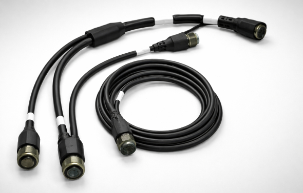
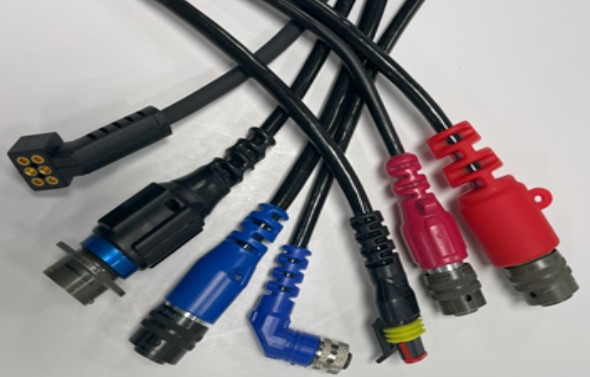
XACT EMS sub miniature connectors series, provide engineers with high-density, reliable connectivity solutions for demanding applications. These connectors boast rugged designs, IP68 sealing, and customizable configurations, making them ideal for industries like medical devices, aerospace, and robotics. With options for power, signal, and data transmission, XACT EMS subminiature connectors offer exceptional performance, EMI/RFI protection, and compact form factors, enabling engineers to optimize space and performance in critical systems.

Value Added

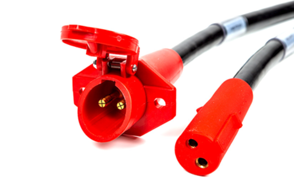
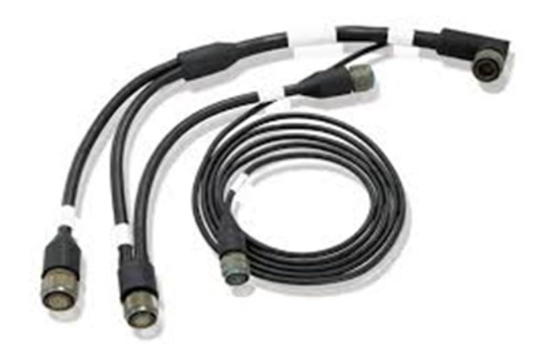
XACT EMS adds significant value to engineering teams by offering not only high-quality connectors but also fully customized harnesses and assemblies. This comprehensive approach streamlines integration, ensures compatibility, and minimizes potential points of failure. XACT EMS specializes in ruggedizing these solutions, employing advanced materials and techniques to enhance durability, shielding, and environmental resilience, ultimately optimizing performance in demanding industrial and military applications.

Frequently Asked Questions

If you have a question that is not addressed in our FAQ please click 'Contact XACT EMS' at the top of the page and submit. We will answer directly and add it to our FAQ to benefit the entire engineering community.

Your vision! Our expertise! Collaborating with engineering teams is what we do best! We listens to your priorities, and create a customized solution tailored to your specific requirements.

1. Push-Pull Subminiature Connectors

  • Description: Push-pull subminiature connectors, like LEMO connectors, feature a self-latching mechanism for secure mating and demating.
  • Primary Benefit for Engineers: Engineers appreciate their robust and quick-connect design, which ensures dependable connections in critical applications, saving time and improving reliability.

2. Snap-In Subminiature Connectors

  • Description: Snap-in subminiature connectors, such as SMB connectors, utilize a snap-on coupling mechanism for efficient assembly.
  • Primary Benefit for Engineers: These connectors simplify installation, reducing labor costs, and offer excellent RF performance for high-frequency applications.

3. Screw-Lock Subminiature Connectors

  • Description: Screw-lock subminiature connectors, like TNC connectors, employ threaded coupling to ensure secure connections.
  • Primary Benefit for Engineers: Engineers value their high mechanical stability, which prevents accidental disconnection and maintains signal integrity.

4. Miniature Circular Connectors

  • Description: Miniature circular connectors, e.g., MIL-DTL-38999, provide compact, circular-shaped designs suitable for aerospace and military applications.
  • Primary Benefit for Engineers: They offer ruggedness and versatility, enabling engineers to accommodate a wide range of signals, power, and data connections in harsh environments.

5. Fiber Optic Subminiature Connectors

  • Description: Fiber optic subminiature connectors, like LC connectors, enable high-speed data transmission via optical fibers.
  • Primary Benefit for Engineers: Engineers benefit from their bandwidth and immunity to electromagnetic interference, making them ideal for data-intensive applications in telecommunications and data centers.

6. Micro-D Connectors

  • Description: Micro-D connectors feature compact rectangular shapes, often used in aerospace and military electronics.
  • Primary Benefit for Engineers: Their miniaturized form factor allows engineers to save space while accommodating a wide range of signal and power connections in constrained environments.

7. High-Temperature Subminiature Connectors

  • Description: High-temperature subminiature connectors, such as ceramic connectors, withstand extreme heat conditions.
  • Primary Benefit for Engineers: These connectors ensure reliability in high-temperature environments, crucial for aerospace, automotive, and industrial applications.

8. Harsh Environment Specialty Connectors

  • Description: Specialty connectors, like Amphenol’s MIL-DTL-38999 Series III, are designed for rugged and demanding environments.
  • Primary Benefit for Engineers: Engineers appreciate their resistance to moisture, chemicals, and physical damage, ensuring consistent performance in challenging applications, such as military and industrial settings.

1. Electrical Properties:

  • Impedance Matching: Ensure the connector’s characteristic impedance matches the transmission line to minimize signal reflection and loss.
  • Voltage and Current Ratings: Select connectors capable of handling the required voltage and current levels without voltage drop or overheating.

2. Signal Integrity:

  • Signal Frequency: Choose connectors designed for the frequency range of the signals being transmitted to maintain signal integrity.
  • Insertion Loss and Return Loss: Evaluate connectors for low insertion loss and high return loss to minimize signal degradation.

3. Environmental Conditions:

  • Operating Temperature: Consider the temperature range in which the connectors will operate and select those rated to withstand extreme temperatures.
  • Moisture and Contaminant Resistance: For harsh environments, opt for connectors with adequate sealing to prevent moisture and contaminants from compromising performance.

4. Mechanical Durability:

  • Mating Cycles: Assess the connector’s durability in terms of mating and unmating cycles, especially in applications where frequent connections are required.
  • Vibration and Shock Resistance: Ensure connectors can withstand mechanical stresses, such as vibrations and shocks, common in aerospace and automotive applications.

5. Size and Form Factor:

  • Space Constraints: Consider the available space for connector installation and select compact sub-miniature connectors that fit within the designated area.
  • Connector Type: Choose connectors that match the form factor and interface requirements of the equipment and system.

6. EMI/RFI Shielding:

  • Electromagnetic Compatibility (EMC): Assess the connector’s effectiveness in providing electromagnetic interference (EMI) and radiofrequency interference (RFI) shielding to prevent signal interference.

7. Material Compatibility:

  • Chemical Resistance: Ensure connectors are resistant to chemicals or substances present in the environment or during cleaning procedures.
  • Corrosion Resistance: Evaluate connectors for resistance to corrosion in corrosive environments.

8. Customization and Special Features:

  • Contact Arrangement: Depending on the application, consider the number and arrangement of contacts, including coaxial, signal, power, and data contacts.
  • Keying and Polarization: Use connectors with keying or polarization features to prevent incorrect mating.
  • Locking Mechanism: Assess the need for locking mechanisms (e.g., push-pull, screw lock) to secure connections in high-vibration scenarios.

9. Compliance and Standards:

  • Industry Standards: Ensure connectors meet relevant industry and military standards, such as MIL-DTL-38999, to guarantee interoperability and performance.
  • Safety Certifications: Verify compliance with safety certifications and regulations, particularly in industries like healthcare and aerospace.

10. Cost and Availability:

  • Cost-Effectiveness: Consider the overall cost of connectors, including procurement, installation, and maintenance.
  • Availability: Ensure a stable supply chain to prevent production disruptions due to component shortages.

1. Medical Devices

  • Problem: Miniaturization is crucial for wearable medical devices and minimally invasive surgical tools, but they require reliable and compact connectors.
  • Solution: Sub-miniature connectors like Fischer MiniMax™ are used in medical applications such as endoscopes and patient monitoring equipment, providing small form factors and secure connections. [Reference: Medical Electronics]

2. Aerospace and Aviation

  • Problem: Space constraints and weight limitations demand lightweight connectors that can withstand harsh environmental conditions.
  • Solution: Micro-D connectors are employed in avionics systems and satellites due to their small size, lightweight design, and robust construction, ensuring reliability in aerospace applications. [Reference: Aerospace Engineering]

3. Automotive Electronics

  • Problem: Automotive electronics require connectors that can handle vibration, shock, and temperature variations.
  • Solution: Sub-miniature connectors like Molex’s MX150™ are used in automotive control units and sensors, offering durability and resistance to harsh automotive environments. [Reference: Automotive Engineering]

4. Telecommunications

  • Problem: High-speed data transmission demands connectors that maintain signal integrity and minimize electromagnetic interference.
  • Solution: Fiber optic sub-miniature connectors, such as LC connectors, provide low-loss, high-bandwidth connections for data centers, telecommunications equipment, and networking applications. [Reference: Telecommunications]

5. Industrial Automation

  • Problem: Industrial automation systems require connectors that can handle high-speed data, power, and signal connections in demanding industrial environments.
  • Solution: Miniature circular connectors are commonly used in industrial automation machinery and robotics, offering ruggedness and versatility for reliable data and power transmission. [Reference: Industrial Automation]

6. Defense and Military Electronics

  • Problem: Military applications demand connectors that can withstand extreme environmental conditions, including temperature variations, shock, and moisture.
  • Solution: Specialty connectors like MIL-DTL-38999 Series III connectors are utilized in military equipment, providing robustness and compliance with military standards for harsh field deployments. [Reference: Defense Industry]

7. Oil and Gas Exploration

  • Problem: Oil and gas exploration requires connectors that can resist corrosion, high temperatures, and pressure differentials.
  • Solution: High-temperature and corrosion-resistant sub-miniature connectors are used in downhole tools and drilling equipment, ensuring reliability in extreme oil and gas environments. [Reference: Oil and Gas Industry]

8. Consumer Electronics

  • Problem: Miniaturization is essential in consumer electronics, such as smartphones and wearables, to create compact and portable devices.
  • Solution: Push-pull sub-miniature connectors are used in consumer electronics, offering space-saving and reliable interconnect solutions for various portable devices. [Reference: Consumer Electronics]

COMPARE

Compare Options

Click below to get a customized comparison chart tailored to your application.

1

2

3

1

2

3

Consideration Brand A Brand B Brand C
Electrical Properties Very Good Good Moderate
Signal Integrity Very Good Good Moderate
Environmental Conditions Good Moderate Very Good
Mechanical Durability Very Good Good Moderate
Size and Form Factor Good Very Good Moderate
EMI/RFI Shielding Good Very Good Moderate
Material Compatibility Good Very Good Moderate
Customization and Special Features Moderate Good Very Good
Compliance and Standards Very Good Good Moderate
Cost and Availability Moderate Good Very Good

Product Description

XACT EMS molded breakouts and splitters offer engineers versatile cable management solutions. Designed with precision, these components provide strain relief, organization, and protection at cable junctions, safeguarding against damage and optimizing cable performance. Commonly used in defense, power distribution, and industrial automation, they enhance cable integrity and simplify maintenance. Their robust construction and customization options make them invaluable tools for optimizing cable systems in demanding industrial settings, ensuring reliability and efficient cable management.

Value Added

XACT EMS excels in crafting innovative molded breakouts and splitters, tailored precisely to your application requirements. Utilizing advanced engineering techniques such as precision molding and specialized materials, XACT EMS ensures optimal cable organization, strain relief, and protection. Engineers benefit from customized solutions, designed to withstand harsh environments. XACT EMS’s expertise in cable management and meticulous manufacturing techniques guarantee the perfect fit for your unique application needs.

Frequently Asked Questions

If you have a question that is not addressed in our FAQ please click 'Contact XACT EMS' at the top of the page and submit. We will answer directly and add it to our FAQ to benefit the entire engineering community.

1. Fiber Optic Molded Breakouts:

  • Description: These provide protection and organization for fiber optic cable terminations.
  • Primary Benefit for Engineers: Ensures precise cable routing, strain relief, and environmental protection for fiber optics in data centers and telecom networks.

2. Electrical Cable Molded Breakouts:

  • Description: Designed for electrical cables, offering strain relief and organization.
  • Primary Benefit for Engineers: Safeguards cable connections, reduces wear, and enhances electrical system reliability, especially in industrial settings.

3. Multi-Cable Splitters:

  • Description: Split multiple cables into individual channels for neat organization.
  • Primary Benefit for Engineers: Simplifies cable management, reduces interference, and eases maintenance in control panels and automation systems.

4. Coaxial Cable Splitters:

  • Description: Divides coaxial cables into separate paths.
  • Primary Benefit for Engineers: Minimizes signal interference, ensuring high-quality RF communication in broadcast and telecommunications.

5. Ruggedized Molded Breakouts:

  • Description: Designed for harsh environments, with added durability and weather resistance.
  • Primary Benefit for Engineers: Ensures reliable cable protection and organization in demanding industrial and outdoor applications.

6. Custom Molded Breakouts:

  • Description: Tailored to specific cable configurations and project requirements.
  • Primary Benefit for Engineers: Offers flexibility to meet unique cable management needs, enhancing organization and reliability.

7. Multi-Fiber Optic Splitters:

  • Description: Splits multiple fiber optic cables into individual channels.
  • Primary Benefit for Engineers: Efficiently manages complex fiber optic connections in data centers, telecom networks, and fiber-to-the-home (FTTH) installations.

8. Specialty Breakouts for High-Temperature Environments:

  • Description: Designed to withstand extreme temperatures.
  • Primary Benefit for Engineers: Ensures cable integrity and reliability in environments with high heat, such as industrial ovens and aerospace applications.

9. HVAC Cable Splitters:

  • Description: Facilitates cable management in heating, ventilation, and air conditioning systems.
  • Primary Benefit for Engineers: Simplifies wiring and maintenance in HVAC control panels and equipment.

10. Instrumentation Molded Breakouts:

  • Description: Organizes and protects cables in measurement and control systems.
  • Primary Benefit for Engineers: Enhances cable integrity, reduces interference, and streamlines troubleshooting in industrial instrumentation applications.

1. Cable Type and Size: Evaluate the cable type (e.g., fiber optic, electrical, coaxial) and size to ensure the breakout or splitter is compatible with the cable’s specifications.

2. Number of Cables: Determine the number of cables that need to be organized or split to select the appropriate breakout or splitter with the required channels.

3. Connector Compatibility: Ensure that the breakout or splitter is compatible with the connectors used on the cables, considering factors like connector type, size, and alignment.

4. Environmental Conditions: Assess the operating environment for temperature extremes, moisture, chemicals, and UV exposure to choose a breakout or splitter with suitable materials and weather resistance.

5. Protection Requirements: Consider the level of protection needed for cable terminations, such as strain relief, dust and moisture resistance, and impact protection.

6. Customization Options: Evaluate whether customization is necessary to meet specific cable routing or organization needs, and whether the chosen breakout or splitter can be tailored accordingly.

7. Electromagnetic Compatibility (EMC): In applications sensitive to electromagnetic interference (EMI), select a breakout or splitter with proper shielding to minimize EMI effects.

8. Mounting and Installation Method: Determine how the breakout or splitter will be mounted and installed in the system, considering factors like panel mounting, adhesive, or cable tie compatibility.

9. Temperature Rating: Ensure that the breakout or splitter can withstand the temperature range of the application, especially in extreme conditions or high-temperature environments.

10. Maintenance and Accessibility: Consider ease of access for maintenance and troubleshooting, ensuring that the chosen breakout or splitter design allows for convenient cable inspection and replacement.

11. Compliance with Standards: Ensure that the selected breakout or splitter complies with industry standards and regulations, such as UL, CE, and RoHS, for safety and environmental requirements.

12. Cost-Benefit Analysis: Balance performance requirements with budget constraints, considering the cost-effectiveness of the chosen breakout or splitter solution.

1. Telecommunications and Data Centers:

  • Problem: Cables in data centers require organized and protected terminations for efficient data transmission.
  • Solution: Molded breakouts provide strain relief, cable organization, and protection for fiber optic and Ethernet cables.
  • Industry/Application: Data centers, telecommunications infrastructure.

2. Oil and Gas Exploration:

  • Problem: Harsh drilling environments expose cables to extreme conditions, risking damage.
  • Solution: Specialty molded breakouts protect cables from chemicals, abrasion, and weather in oil and gas applications.
  • Industry/Application: Drilling equipment, offshore platforms.

3. Industrial Automation and Control Systems:

  • Problem: Complex machinery and control systems require organized and reliable cable terminations.
  • Solution: Molded breakouts offer cable organization, strain relief, and protection for power and data cables.
  • Industry/Application: Manufacturing automation, robotics, industrial control panels.

4. Aerospace and Avionics:

  • Problem: Aircraft avionics require durable and secure cable terminations.
  • Solution: Molded breakouts ensure cable integrity and protection against vibration and harsh conditions.
  • Industry/Application: Aircraft avionics, military aircraft.

5. Marine and Offshore Applications:

  • Problem: Marine environments subject cables to saltwater and corrosion.
  • Solution: Ruggedized molded breakouts provide weatherproofing and cable organization for marine cables.
  • Industry/Application: Shipboard systems, offshore platforms.

6. Railway and Transportation Systems:

  • Problem: Rail systems demand organized and protected cable connections for safety and reliability.
  • Solution: Molded breakouts offer cable management and strain relief for railway signaling and communication systems.
  • Industry/Application: Rail transportation, signaling systems.

7. Renewable Energy Systems:

  • Problem: Solar and wind installations require organized cable terminations in outdoor environments.
  • Solution: Molded breakouts protect cables against UV exposure and weather conditions.
  • Industry/Application: Solar panel installations, wind farms.

8. Mining and Mineral Processing:

  • Problem: Mining operations expose cables to abrasive and corrosive environments.
  • Solution: Specialty molded breakouts safeguard cables from harsh conditions in mining equipment.
  • Industry/Application: Mining machinery, mineral processing.

9. Medical Equipment and Devices:

  • Problem: Medical devices require sterile and organized cable terminations.
  • Solution: Molded breakouts offer cable organization and protection for medical cables.
  • Industry/Application: Medical device manufacturing, diagnostic equipment.

10. Environmental Monitoring Systems:

  • Problem: Environmental sensors and monitoring equipment need cable organization in outdoor settings.
  • Solution: Molded breakouts protect cables from exposure to the elements and offer strain relief.
  • Industry/Application: Environmental monitoring, weather stations.

COMPARE

Compare Options

Click below to get a customized comparison chart tailored to your application.

1

2

3

1

2

3

Consideration Fiber Optic Molded Breakout Electrical Cable Molded Breakout Ruggedized Molded Breakout C
Cable Type Compatibility Very Good Very Good Very Good
Connector Compatibility Very Good Very Good Very Good
Environmental Durability Good Moderate Very Good
Protection Requirements Very Good Good Very Good
Customization Options Very Good Good Good
EMC/EMI Mitigation Good Moderate Very Good
Mounting and Installation Very Good Very Good Good
Temperature Rating Good Good Very Good
Maintenance and Accessibility Good Good Very Good
Cost-Benefit Analysis Moderate Very Good Good

Product Description

XACT EMS rugged and harsh environment cable assembly solutions excel in challenging conditions, featuring robust construction, resistance to moisture, chemicals, and temperature extremes. Engineers benefit from enhanced reliability, durability, and signal integrity, ideal for industries like aerospace, oil and gas, and automotive manufacturing. These cable assemblies adhere to stringent standards, ensuring uninterrupted performance in mission-critical applications, while offering customization options to suit diverse engineering needs, facilitating efficient connectivity and durability in extreme environments.

Value Added

XACT EMS engineers rugged cable assemblies with meticulous attention to detail, utilizing advanced materials like UV-resistant jackets and precision overmolding for environmental resilience. Employing techniques such as potting and strain relief, XACT EMS ensures optimal strain resistance and electrical performance. Engineers benefit from durable, customized solutions that withstand harsh conditions, reducing downtime and maintenance efforts, while maintaining consistent signal integrity in demanding applications

Frequently Asked Questions

If you have a question that is not addressed in our FAQ please click 'Contact XACT EMS' at the top of the page and submit. We will answer directly and add it to our FAQ to benefit the entire engineering community.

Your vision! Our expertise! Collaborating with engineering teams is what we do best! We listens to your priorities, and create a customized solution tailored to your specific requirements.

1. High-Temperature Cable Assemblies:

  • Description: Designed for extreme heat environments.
  • Primary Benefit for Engineers: Maintains signal integrity and reliability in high-temperature industrial processes and equipment.

2. Oil and Chemical Resistant Cable Assemblies:

  • Description: Resistant to oil, chemicals, and solvents.
  • Primary Benefit for Engineers: Ensures cable integrity and longevity in oil and chemical processing plants.

3. Waterproof and Submersible Cable Assemblies:

  • Description: Sealed against water and submersion.
  • Primary Benefit for Engineers: Ideal for marine, underwater, and outdoor applications, safeguarding against moisture and corrosion.

4. EMI/RFI Shielded Cable Assemblies:

  • Description: Provides electromagnetic and radiofrequency interference protection.
  • Primary Benefit for Engineers: Maintains signal quality and prevents interference in sensitive electronics and data transmission.

5. Abrasion-Resistant Cable Assemblies:

  • Description: Withstands physical abrasion and wear.
  • Primary Benefit for Engineers: Enhances cable longevity in rugged industrial machinery and harsh environments.

6. Vibration-Resistant Cable Assemblies:

  • Description: Designed to withstand vibrations.
  • Primary Benefit for Engineers: Ensures stable electrical connections in machinery exposed to vibrations, reducing downtime.

7. Fire-Resistant Cable Assemblies:

  • Description: Resistant to flames and high temperatures.
  • Primary Benefit for Engineers: Provides fire protection for critical applications like aerospace and rail systems.

8. Solar and UV-Resistant Cable Assemblies:

  • Description: UV-stable materials for outdoor solar installations.
  • Primary Benefit for Engineers: Maintains cable integrity in solar panels, even in direct sunlight.

9. Shock-Resistant Cable Assemblies:

  • Description: Withstands mechanical shocks and impacts.
  • Primary Benefit for Engineers: Ensures cable reliability in applications prone to physical shocks, like automotive and military.

10. Customized Specialty Cable Assemblies:

  • Description: Tailored to specific project requirements.
  • Primary Benefit for Engineers: Offers flexibility to meet unique application needs, optimizing cable performance and durability.

1. Environmental Conditions: Evaluate the operating environment, including temperature extremes, humidity, exposure to chemicals, UV radiation, water, and dust.

2. Material Selection: Choose materials that can withstand environmental factors and are resistant to chemicals, abrasion, and UV exposure.

3. Cable Jacket and Insulation: Select ruggedized cable jackets and insulation materials suitable for the environment and temperature range.

4. Connectors and Terminations: Use connectors and terminations designed for harsh environments, ensuring secure connections and protection against moisture and dust ingress.

5. Strain Relief and Cable Entry: Implement strain relief mechanisms to prevent cable damage due to bending, twisting, or pulling. Ensure proper cable entry seals to prevent environmental contaminants from entering the assembly.

6. Shielding: Include appropriate shielding to protect against electromagnetic interference (EMI) and radiofrequency interference (RFI).

7. Connector Sealing and Gaskets: Use sealing materials and gaskets to create a watertight and dustproof seal at connector interfaces.

8. Vibration and Shock Resistance: Design cable assemblies to withstand vibrations and mechanical shocks encountered in rugged applications.

9. Flex Life and Bend Radius: Ensure cable assemblies can endure repeated flexing and bending without damage.

10. Compliance with Standards: Verify that the design complies with industry-specific standards and regulations for ruggedized cable assemblies.

11. Testing and Quality Control: Implement rigorous testing protocols, including environmental testing (e.g., temperature cycling, vibration testing) to validate performance under harsh conditions.

12. Customization: Tailor the cable assembly to meet specific application requirements, including cable length, connectors, and breakout options.

13. Serviceability and Repair ability: Design the assembly to allow for ease of maintenance and repair in the field, reducing downtime.

14. Cost Optimization: Balance ruggedization measures with cost considerations, ensuring a cost-effective solution without compromising performance.

15. Cable Routing and Management: Plan cable routing within the equipment or system to minimize exposure to environmental hazards.

16. IP Ratings: Consider IP (Ingress Protection) ratings to ensure the assembly’s resistance to dust and water intrusion.

17. Chemical Compatibility: Assess the compatibility of cable materials with any chemicals present in the environment.

1. Aerospace and Defense:

  • Problem: Extreme temperatures, vibrations, and electromagnetic interference in aircraft and military equipment.
  • Solution: Ruggedized cable assemblies withstand harsh conditions, ensuring reliable data and power connections.
  • Industry/Application: Avionics, military vehicles, communication systems.

2. Oil and Gas Exploration:

  • Problem: Corrosive chemicals, abrasion, and extreme weather in drilling and extraction operations.
  • Solution: Ruggedized cables resist chemicals and protect against mechanical wear and environmental factors.
  • Industry/Application: Drilling equipment, offshore platforms.

3. Automotive Manufacturing:

  • Problem: Robotic automation and welding environments subject cables to mechanical stress and high temperatures.
  • Solution: Ruggedized cable assemblies withstand heat and offer strain relief, enhancing automation reliability.
  • Industry/Application: Automotive assembly lines, welding robots.

4. Mining and Mineral Processing:

  • Problem: Abrasion, dust, and vibrations in mining equipment.
  • Solution: Specialty ruggedized cables endure harsh mining conditions, reducing maintenance.
  • Industry/Application: Mining machinery, mineral extraction.

5. Marine and Offshore Applications:

  • Problem: Saltwater, moisture, and UV exposure in marine environments.
  • Solution: Waterproof and UV-resistant cable assemblies safeguard against corrosion and weather.
  • Industry/Application: Shipboard systems, offshore platforms.

6. Railway and Transportation Systems:

  • Problem: Vibrations, temperature fluctuations, and exposure to elements.
  • Solution: Ruggedized cables ensure reliable connections in railway signaling, communication, and control systems.
  • Industry/Application: Rail transportation, signaling systems.

7. Renewable Energy Systems:

  • Problem: Outdoor exposure, temperature variations, and UV radiation in solar and wind installations.
  • Solution: Solar- and UV-resistant cable assemblies maintain performance in renewable energy systems.
  • Industry/Application: Solar farms, wind turbines.

8. Industrial Automation and Robotics:

  • Problem: Extreme temperatures, mechanical stress, and vibrations in automated machinery.
  • Solution: Ruggedized cables enhance cable longevity and ensure reliable automation.
  • Industry/Application: Manufacturing automation, robotics.

9. Outdoor Telecommunications Infrastructure:

  • Problem: Exposure to weather, moisture, and temperature fluctuations.
  • Solution: Waterproof and weather-resistant cable assemblies protect outdoor telecom infrastructure.
  • Industry/Application: Telecom towers, outdoor networking.

10. Harsh Laboratory Environments:

  • Problem: Chemical exposure, temperature fluctuations, and mechanical stress.
  • Solution: Chemical-resistant and high-temperature cables endure lab conditions.
  • Industry/Application: Scientific research, laboratory equipment.

COMPARE

Compare Options

Click below to get a customized comparison chart tailored to your application.

1

2

3

1

2

3

Consideration Harsh & Rugged Cable Assembly A Harsh & Rugged Cable Assembly B Harsh & Rugged Cable Assembly C
Environmental Resistance Very Good Good Very Good
Material Durability Very Good Very Good Good
Connector and Termination Very Good Very Good Good
EMI/RFI Shielding Very Good Good Very Good
Temperature Range Very Good Good Very Good
Vibration and Shock Resistance Very Good Good Good
Chemical Resistance Good Good Very Good
IP Rating Very Good Good Very Good
Customization Options Good Very Good Moderate
Cost-Efficiency Moderate Good Moderate

Product Description

XACT EMS automated cordsets offer engineers precise connectivity solutions. These cordsets feature high-quality materials and conform to industry standards, ensuring reliability and seamless integration in industrial automation applications. Engineers benefit from the flexibility of data, control, and motor connection cordsets, customizable to meet diverse automation requirements. With resistance to environmental factors and a broad range of applications, XACT EMS cordsets are a dependable choice for engineers seeking robust industrial connectivity.

Value Added

XACT EMS tailors solutions to match your specific needs. We have the capability to design and manufacture a fully integrated, plug-and-play solution for your application, leveraging our expertise in various cable types and connectors, including specialized manufacturing techniques, that we’ve successfully employed in numerous automation technology projects to your advantage.

Frequently Asked Questions

If you have a question that is not addressed in our FAQ please click 'Contact XACT EMS' at the top of the page and submit. We will answer directly and add it to our FAQ to benefit the entire engineering community.

Your vision! Our expertise! Collaborating with engineering teams is what we do best! We listens to your priorities, and create a customized solution tailored to your specific requirements.

1. Highly Flexible Chain Cables:

  • Description: Highly flexible chain cables are designed for use in cable carriers or drag chains, offering durability in dynamic applications.
  • Primary Benefit: They withstand constant bending and flexing, reducing downtime and maintenance costs in automation systems.

2. Servo Cables:

  • Description: Servo cables are engineered for connecting servo motors and drives, providing precise motion control.
  • Primary Benefit: They offer low capacitance and interference resistance, ensuring accurate and reliable servo motor operation.

3. Sensor-/Actuator Cables and Wires:

  • Description: Sensor-/actuator cables and wires link sensors and actuators to control systems for data acquisition and actuation.
  • Primary Benefit: They enable efficient signal transmission, facilitating automation and control processes.

4. Optical Waveguide Cables and Wires:

  • Description: Optical waveguide cables and wires transmit data via light signals, suitable for high-speed data communication.
  • Primary Benefit: They provide high bandwidth and immunity to electromagnetic interference, ideal for demanding automation networks.

5. Torsionable Cables and Wires:

  • Description: Torsionable cables and wires are designed for applications involving twisting or torsional movements.
  • Primary Benefit: They maintain signal integrity and prevent cable damage in rotating equipment.

6. Flexible Tray Cables and Wires:

  • Description: Flexible tray cables and wires are suitable for use in cable trays and conduit systems.
  • Primary Benefit: They offer versatility in cable routing and protection, simplifying installation in automation setups.

7. High Flex Control Cables and Wires:

  • Description: High flex control cables and wires provide reliable control signal transmission in dynamic environments.
  • Primary Benefit: They endure repeated flexing, reducing downtime and maintenance requirements.

8. Bus Cables for Industrial Communication:

  • Description: Bus cables support various industrial communication protocols like Profibus or Modbus.
  • Primary Benefit: They facilitate efficient data exchange in automation networks, enhancing control and monitoring capabilities.

9. CAT 5 Cables and Wires:

  • Description: CAT 5 cables and wires are Ethernet cables capable of transmitting data at up to 100 Mbps.
  • Primary Benefit: They offer reliable data connectivity, suitable for many industrial applications.

10. CAT 6 and CAT 6A Cables and Wires:

  • Description: CAT 6 and CAT 6A cables provide higher data transmission speeds (up to 10 Gbps) compared to CAT 5.
  • Primary Benefit: They support faster data communication, ideal for demanding industrial Ethernet networks.

11. Industrial Gigabit Ethernet Cables – Single Pair Ethernet Cables:

  • Description: Industrial Gigabit Ethernet cables deliver Gigabit data rates over single pairs of conductors.
  • Primary Benefit: They provide high-speed Ethernet connectivity for industrial automation applications.

12. Cables and Wires CAT 6A and CAT 7A:

  • Description: CAT 6A and CAT 7A cables offer enhanced data transmission performance for industrial networks.
  • Primary Benefit: They ensure high bandwidth and reliability, supporting critical data-intensive processes in automation.

These cordsets and cables cater to specific automation needs, offering durability, signal integrity, and data transmission capabilities for various industrial applications.

1. Application Requirements:

  • Understand the specific needs and function of the cordset within the automation system.

2. Environmental Conditions:

  • Determine the operating environment, including temperature ranges, exposure to moisture, chemicals, and physical stress.

3. Electrical Requirements:

  • Identify voltage ratings, current capacity, and signal type (e.g., data, power) to select appropriate conductors and insulation.

4. Connector Type and Compatibility:

  • Choose connectors compatible with the equipment, ensuring secure and reliable connections.

5. Cable Type and Material:

  • Select the appropriate cable type (e.g., PVC, PUR, TPE) and material based on environmental and electrical requirements.

6. Cable Length and Configuration:

  • Specify the cordset’s length and connector configurations to meet installation and space constraints.

7. Flexibility and Flex Life:

  • Consider the need for flexibility and the number of flex cycles the cordset must endure, especially in dynamic applications.

8. Shielding and EMI/RFI Protection:

  • Determine if shielding is necessary to protect against electromagnetic interference (EMI) and radiofrequency interference (RFI).

9. Safety Standards Compliance:

  • Ensure the cordset meets industry-specific safety standards and regulations.

10. Customization Options:

  • Evaluate the availability of customizable options to tailor the cordset to specific requirements.

11. Connector Sealing and IP Rating:

  • Consider the level of sealing and IP rating required to protect against dust and moisture.

12. Abrasion and Chemical Resistance:

  • Assess the cordset’s resistance to abrasion, chemicals, oils, and other potential hazards in the environment.

13. Torsional Movement:

  • For applications involving twisting or torsional movement, choose cordsets designed to withstand such stress.

14. Connector Locking Mechanism:

  • Determine if a locking mechanism is necessary to secure connectors in place.

15. Testing and Quality Assurance:

  • Plan for testing and quality control measures to ensure the cordset’s performance and reliability.

16. Cost Considerations:

  • Balance performance requirements with budget constraints to optimize cost-effectiveness.

17. Supplier and Manufacturing Capabilities:

  • Collaborate with a reputable manufacturer with expertise in cordset design and production.

18. Documentation and Drawings:

  • Maintain detailed documentation and drawings to support installation and troubleshooting.

1. Factory Automation and Robotics:

  • Problem: High-speed data transmission and power distribution are essential for automated machinery and robots.
  • Solution: Automation cordsets facilitate reliable signal and power transfer in these dynamic systems, enhancing manufacturing efficiency. (Reference: Manufacturing Industry)

2. Industrial Ethernet Networks:

  • Problem: Data communication in industrial Ethernet networks demands reliable and high-speed connectivity.
  • Solution: Ethernet cordsets provide efficient data transmission, enabling real-time monitoring and control in industrial automation. (Reference: Industrial Networking)

3. Sensor and Actuator Connections:

  • Problem: Sensors and actuators require dependable connections for data acquisition and control.
  • Solution: Sensor/actuator cordsets ensure secure and efficient signal transmission in automation systems. (Reference: Automation Control)

4. Motor and Drive Connections:

  • Problem: Motors and drives require precision control signals and power supply.
  • Solution: Servo and motor cordsets deliver accurate control and power distribution for motion control applications. (Reference: Motion Control)

5. Machine Tools and CNC Equipment:

  • Problem: CNC machines demand high-flexibility cables for precise and rapid movement.
  • Solution: Highly flexible chain cables provide durability and signal integrity, enhancing machining accuracy. (Reference: Machining Industry)

6. Industrial Robotics:

  • Problem: Robots in manufacturing and assembly lines require robust and reliable connections.
  • Solution: Automation cordsets withstand repeated flexing, ensuring uninterrupted robot operation. (Reference: Robotics Industry)

7. Control Panels and PLCs:

  • Problem: Control panels and PLCs need structured connections for process control.
  • Solution: Control cables and tray cables simplify installation and organization, supporting control system reliability. (Reference: Control Systems)

8. Material Handling Systems:

  • Problem: Conveyor systems and material handling equipment demand resilient cables.
  • Solution: Torsionable cables endure twisting movements, reducing cable wear and maintenance. (Reference: Material Handling)

9. Automotive Manufacturing:

  • Problem: Automotive assembly lines require fast and reliable connectivity for automation.
  • Solution: Automation cordsets facilitate precise control and monitoring in automotive production. (Reference: Automotive Industry)

10. Food and Beverage Processing:

  • Problem: Harsh washdowns and hygiene requirements challenge cable durability.
  • Solution: Cordsets with IP-rated connectors and materials withstand washdowns in food processing plants. (Reference: Food Industry)

COMPARE

Compare Options

Click below to get a customized comparison chart tailored to your application.

1

2

3

1

2

3

Environmental Resistance Very Good Good Moderate
Flexibility and Flex Life Good Very Good Moderate
Shielding and EMI/RFI Protection Very Good Good Moderate
Connector Durability Good Moderate Very Good
Customization Options Very Good Moderate Good
Torsional Movement Capability Good Moderate Very Good
Temperature Range Very Good Good Moderate
Abrasion and Chemical Resistance Good Very Good Moderate
Compliance with Industry Standards Very Good Good Moderate
Cost-Effectiveness Moderate Good Very Good

Product Description

XACT EMS comprehensive range of custom cable assemblies includes harnesses, ribbon cable assemblies, and overmolded cable solutions, providing engineers with tailored connectivity solutions for various industries. Engineered with precision and utilizing high-quality materials, our assemblies deliver exceptional durability and signal integrity. They are frequently deployed in industries that require seamless integration, EMI/RFI shielding, ruggedization, and adherence to industry standards, making XACT EMS cable assemblies the top choice for engineers in need of reliable, customized interconnect solutions.

Value Added

XACT EMS excels in customizing cable assemblies for demanding environments and critical applications. Using advanced manufacturing techniques like overmolding and potting, XACT EMS ensures superior ruggedization, moisture resistance, and EMI/RFI shielding. Engineers benefit from tailored solutions, including specialized connectors and precise cable lengths, optimizing performance in applications where reliability and durability are paramount.

Frequently Asked Questions

If you have a question that is not addressed in our FAQ please click 'Contact XACT EMS' at the top of the page and submit. We will answer directly and add it to our FAQ to benefit the entire engineering community.

Your vision! Our expertise! Collaborating with engineering teams is what we do best! We listens to your priorities, and create a customized solution tailored to your specific requirements.

1. Custom Wiring Harness:

  • Description: Complex assemblies with multiple connectors, ideal for intricate interconnections.
  • Primary Benefit for Engineers: Streamlined wiring, reduced installation time, and simplified maintenance in applications like automotive and industrial machinery.

2. Ribbon Cable Assemblies:

  • Description: Flat, parallel cables with connectors suitable for data and signal transmission.
  • Primary Benefit for Engineers: High-density, space-saving solutions for PCB connections in electronics and computing.

3. Overmolded Cable Assemblies:

  • Description: Cables encapsulated with protective material for enhanced durability.
  • Primary Benefit for Engineers: Increased resistance to environmental factors, mechanical stress, and chemical exposure in harsh environments.

4. Ruggedized Cable Assemblies:

  • Description: Cables designed for durability in challenging environments.
  • Primary Benefit for Engineers: Exceptional robustness and reliability in applications such as aerospace, military, and industrial automation.

5. Fiber Optic Cable Assemblies:

  • Description: Cables designed for high-speed optical data transmission.
  • Primary Benefit for Engineers: Exceptional bandwidth, immunity to EMI/RFI, and long-distance data transmission for telecommunications and data centers.

6. Coaxial Cable Assemblies:

  • Description: Cables with inner and outer conductors for high-frequency signal transmission.
  • Primary Benefit for Engineers: Low signal loss, excellent EMI/RFI shielding, and precise impedance control for RF and microwave applications.

7. Power Cable Assemblies:

  • Description: Cables designed to handle high voltage and current for power transmission.
  • Primary Benefit for Engineers: Reliable power distribution, reduced heat generation, and enhanced safety in industrial and energy sectors.

8. High-Speed Data Cable Assemblies:

  • Description: Cables optimized for high-speed data transfer, often with impedance-matched designs.
  • Primary Benefit for Engineers: High bandwidth, minimal signal distortion, and EMI/RFI shielding for data-intensive applications, including servers and networking equipment.

9. RF Cable Assemblies:

  • Description: Cables designed for radio frequency applications with precise impedance control.
  • Primary Benefit for Engineers: Exceptional RF signal transmission, minimizing signal loss and providing robust EMI/RFI shielding for telecommunications and wireless systems.

10. EMI/RFI Shielded Cable Assemblies:

  • Description: Cables with specialized shielding to minimize electromagnetic interference (EMI) and radiofrequency interference (RFI).
  • Primary Benefit for Engineers: Effective EMI/RFI protection, ensuring signal integrity in sensitive applications, including aerospace, medical devices, and military electronics.

1. Application Requirements: Understand the specific needs and environment in which the cable assembly will operate.

2. Signal and Data Requirements: Determine the type and bandwidth of signals or data to be transmitted.

3. Voltage and Current Levels: Identify the voltage and current ratings required for power transmission.

4. Connector Types and Compatibility: Select connectors compatible with the equipment and systems the assembly will connect to.

5. Cable Type and Material: Choose the appropriate cable type (e.g., coaxial, twisted pair, fiber optic) and material (e.g., PVC, Teflon) based on the application’s electrical and environmental requirements.

6. Shielding and EMI/RFI Protection: Determine the need for shielding to prevent electromagnetic interference (EMI) and radiofrequency interference (RFI).

7. Temperature and Environmental Conditions: Consider the operating temperature range and exposure to moisture, chemicals, and physical stress.

8. Mechanical Durability: Evaluate the need for ruggedization to withstand vibration, shock, and mechanical wear.

9. Custom Length and Configuration: Specify the exact cable length and connector configurations required for the application.

10. Compliance and Standards: Ensure the cable assembly complies with industry standards and safety regulations.

11. Cost Considerations: Balance performance requirements with cost constraints to meet budget goals.

12. Testing and Quality Assurance: Plan for testing and quality control measures to ensure the cable assembly meets specifications and reliability expectations.

13. Future Expansion and Upgrades: Consider future scalability and the potential need for modifications or upgrades.

14. Supplier and Manufacturing Capabilities: Partner with a reputable manufacturer with the expertise and equipment to produce high-quality custom cable assemblies.

15. Documentation and Drawings: Maintain detailed documentation and drawings for the cable assembly’s design and specifications.

16. Prototyping: Consider prototyping to verify the design and functionality before full-scale production.

17. Lead Times and Availability: Verify the availability of components and materials to prevent production delays.

1. Medical Devices

  • Problem: Medical equipment requires precise, sterilizable, and biocompatible cables for patient monitoring and diagnostic devices.
  • Solution: Custom medical cable assemblies, with specialized connectors and materials, ensure compliance with stringent medical standards, supporting accurate data transmission in healthcare settings. [Reference: Medical Electronics]

2. Telecommunications and Data Centers

  • Problem: High-speed data transmission demands cables with minimal signal loss and electromagnetic interference.
  • Solution: Custom high-speed data cable assemblies, with impedance-matched designs and shielding, provide high bandwidth and EMI/RFI protection for telecommunications infrastructure and data centers. [Reference: Telecommunications]

3. Aerospace and Aviation

  • Problem: Aerospace applications require lightweight, high-performance cables that withstand extreme temperatures and mechanical stresses.
  • Solution: Custom aerospace cable assemblies, featuring specialized connectors and lightweight materials, ensure reliable data and power transmission in aircraft avionics systems. [Reference: Aerospace Engineering]

4. Automotive Electronics

  • Problem: Automotive electronics demand cables capable of withstanding vibration, temperature variations, and exposure to chemicals.
  • Solution: Custom automotive cable assemblies, with durable connectors and automotive-grade materials, support reliable connections and signal transmission in vehicle control units and sensors. [Reference: Automotive Engineering]

5. Industrial Automation and Robotics

  • Problem: Industrial machinery requires custom cables that endure high-speed motion, harsh chemicals, and temperature fluctuations.
  • Solution: Custom industrial cable assemblies, featuring high-flex cables and robust connectors, ensure reliable data and power transmission in automated manufacturing and robotic systems. [Reference: Industrial Automation]

6. Defense and Military Electronics

  • Problem: Military equipment operates in extreme environments, demanding rugged, secure, and high-performance cables.
  • Solution: Custom military cable assemblies, compliant with military standards and featuring specialized connectors and shielding, support data and power transmission in field-deployed military electronics. [Reference: Defense Industry]

7. Oil and Gas Exploration

  • Problem: Downhole tools in oil and gas drilling require custom cables that endure extreme temperatures, high pressures, and corrosive fluids.
  • Solution: Custom downhole cable assemblies, designed with high-temperature insulation and corrosion-resistant materials, support reliable connectivity for efficient drilling operations. [Reference: Oil and Gas Industry]

8. Marine and Offshore Applications

  • Problem: Marine and offshore equipment face saltwater corrosion, humidity, and mechanical stress.
  • Solution: Custom marine cable assemblies, with marine-grade connectors and coatings, ensure reliable communication and control in marine and offshore environments. [Reference: Marine Industry]

9. Consumer Electronics

  • Problem: Consumer electronics require compact and reliable custom cables for portable devices and wearables.
  • Solution: Custom consumer electronic cable assemblies, with small form factors and specialized connectors, offer seamless interconnectivity in smartphones, wearables, and handheld devices. [Reference: Consumer Electronics]

COMPARE

Compare Options

Click below to get a customized comparison chart tailored to your application.

1

2

3

1

2

3

Consideration Type A Performance Type B Performance Type C Performance
Signal Integrity Very Good Good Moderate
EMI/RFI Shielding Good Very Good Moderate
Environmental Resistance Moderate Good Very Good
Temperature Range Good Moderate Very Good
Customization Options Very Good Good Moderate
Connector Compatibility Good Moderate Very Good
Mechanical Durability Very Good Good Moderate
Cost-Effectiveness Moderate Good Very Good
Lead Times and Availability Good Moderate Very Good
Compliance with Standards Very Good Good Moderate

Product Description

Custom overmolded cables, designed by XACT EMS, are a vital engineering solution for applications demanding durability and reliability. These cables feature precision overmolding, ensuring robust protection against environmental factors, mechanical stress, and electromagnetic interference. Engineers benefit from tailored configurations, meeting specific voltage, current, and signal requirements. Ideal for industries such as defense, aerospace, instrumentation and industrial automation, overmolded cables excel in harsh environments, offering long-lasting performance and secure connections, making them a cornerstone of modern engineering projects.

Value Added

XACT EMS enhances engineering projects with custom overmolded harnesses and assemblies, leveraging smart cables and bespoke molds. This value addition includes precision tailoring to meet unique voltage, current, and signal requirements, ensuring robust, ruggedized solutions. By protecting against environmental stressors and electromagnetic interference, XACT EMS’s custom overmolding significantly enhances reliability and longevity in demanding applications, empowering engineering teams to optimize performance and durability.

Frequently Asked Questions

If you have a question that is not addressed in our FAQ please click 'Contact XACT EMS' at the top of the page and submit. We will answer directly and add it to our FAQ to benefit the entire engineering community.

Your vision! Our expertise! Collaborating with engineering teams is what we do best! We listens to your priorities, and create a customized solution tailored to your specific requirements.

1. Standard Overmolded Cable Assemblies:

  • Description: These assemblies feature a standard overmolded design for added protection and durability.
  • Primary Benefit for Engineers: Engineers benefit from enhanced mechanical strength and resistance to environmental factors, ensuring long-term reliability in a wide range of applications.

2. Custom Overmolded Cable Assemblies:

  • Description: Tailored to precise specifications, these assemblies provide a bespoke solution for unique engineering requirements.
  • Primary Benefit for Engineers: Customization allows engineers to optimize cable configurations, ensuring compatibility with specific voltage, current, and signal needs.

3. Ruggedized Overmolded Cable Assemblies:

  • Description: Designed to withstand extreme conditions, these assemblies offer superior ruggedness.
  • Primary Benefit for Engineers: Engineers gain the ability to deploy cables in harsh environments, ensuring consistent performance and reducing downtime.

4. Shielded Overmolded Cable Assemblies:

  • Description: These assemblies feature electromagnetic shielding to minimize interference.
  • Primary Benefit for Engineers: Engineers can maintain signal integrity and reduce the risk of electromagnetic interference in sensitive applications.

5. Smart Overmolded Cable Assemblies:

  • Description: Incorporating smart technology, these assemblies provide data transmission and monitoring capabilities.
  • Primary Benefit for Engineers: Engineers can collect real-time data, enabling predictive maintenance, remote monitoring, and enhanced control in IoT and automation systems.

6. High-Flex Overmolded Cable Assemblies:

  • Description: Engineered for repeated bending and flexing, these assemblies excel in dynamic applications.
  • Primary Benefit for Engineers: These cables ensure longevity and reliability in applications requiring frequent movement and flexing, such as robotics.

7. Specialty Overmolded Cable Assemblies:

  • Description: Tailored for specific industries or applications, these assemblies address unique engineering challenges.
  • Primary Benefit for Engineers: Engineers gain access to specialized solutions, precisely crafted to meet the demands of their industry or application, improving performance and efficiency.

1. Cable Selection: Engineers should choose the appropriate cable type, considering factors such as conductor material, gauge, insulation, and shielding to meet the electrical and mechanical requirements of the application.

2. Overmolding Material: Selecting the right overmolding material, such as thermoplastic or thermoset, is crucial. It should match the cable’s material compatibility, provide adequate protection, and meet environmental requirements.

3. Mold Design: The mold design must accommodate the cable’s size and shape while ensuring proper strain relief, stress distribution, and a secure fit. Mold geometry should prevent air entrapment during the molding process.

4. Strain Relief and Flexibility: Incorporating strain relief features within the overmold design is essential to prevent cable damage at the junction between the cable and overmold. Ensure that the design allows for cable flexibility as needed for the application.

5. Environmental Considerations: Assess the environmental conditions the assembly will be exposed to, such as temperature extremes, moisture, chemicals, and UV radiation. Select materials that can withstand these conditions.

6. Connector Compatibility: Ensure that the overmolded assembly is compatible with the connectors it needs to interface with. Proper alignment and secure attachment are critical for electrical connectivity.

7. Electromagnetic Compatibility (EMC): In applications sensitive to electromagnetic interference (EMI), incorporate shielding within the overmold design to minimize EMI effects and maintain signal integrity.

8. Cable Stranding and Flex Life: Consider the cable stranding type (e.g., solid, stranded, or fine-stranded) and its impact on flexibility and fatigue resistance. Choose stranding that suits the application’s flex life requirements.

9. Testing and Quality Control: Implement thorough testing protocols, including continuity, insulation resistance, and high-potential testing, to ensure the assembly meets performance and safety standards.

10. Customization: If the application demands custom features, such as integrated sensors or connectors, engineer the overmold to accommodate these components seamlessly.

11. Cost Optimization: Balance performance requirements with cost constraints by optimizing material selection and manufacturing processes while maintaining reliability.

12. Assembly Process: Consider the assembly process, including molding techniques (compression, injection, or transfer molding), curing times, and quality control procedures to ensure consistency and reliability.

13. Serviceability and Repairability: Design with future maintenance and repair in mind, making it easier to replace components or perform repairs without extensive disassembly.

1. Automotive Wiring Harnesses:

  • Problem: Vibration, temperature fluctuations, and exposure to moisture can damage vehicle wiring.
  • Solution: Overmolded cable assemblies provide robust protection, ensuring long-term reliability in automotive applications.
  • Industry/Application: Automotive manufacturing and electric vehicle (EV) charging systems.

2. Industrial Automation and Robotics:

  • Problem: High flexing and repetitive motion can lead to cable fatigue and failure.
  • Solution: High-flex overmolded cables are designed for repeated bending, ensuring continuous operation in automation and robotic systems.
  • Industry/Application: Manufacturing automation and robotic arms.

3. Aerospace and Aviation:

  • Problem: Aerospace environments subject cables to extreme temperature variations and electromagnetic interference.
  • Solution: Shielded overmolded cable assemblies protect against EMI, ensuring reliable data transmission in avionics systems.
  • Industry/Application: Aircraft avionics and communication systems.

4. Medical Devices:

  • Problem: Medical equipment requires sterile and durable cabling.
  • Solution: Custom overmolded cables with medical-grade materials ensure reliability in medical devices, including diagnostic equipment and patient monitors.
  • Industry/Application: Medical device manufacturing.

5. Renewable Energy Systems:

  • Problem: Solar and wind installations face outdoor exposure and harsh weather conditions.
  • Solution: Ruggedized overmolded cables protect against UV radiation, moisture, and extreme temperatures in renewable energy systems.
  • Industry/Application: Solar panel connections and wind turbine installations.

6. IoT and Smart Devices:

  • Problem: IoT devices require compact, secure, and customizable cabling solutions.
  • Solution: Smart overmolded cable assemblies offer data transmission, security, and customization for IoT applications.
  • Industry/Application: IoT sensors and smart home devices.

7. Oil and Gas Exploration:

  • Problem: Harsh drilling environments subject cables to extreme conditions.
  • Solution: Specialty overmolded cables are designed for oil and gas applications, providing durability and resistance to chemicals and abrasion.
  • Industry/Application: Oil and gas drilling equipment.

8. Military and Defense:

  • Problem: Military equipment requires rugged and reliable cable assemblies in harsh combat environments.
  • Solution: Customized overmolded cables meet military standards, ensuring secure communications and equipment functionality.
  • Industry/Application: Military communications and defense systems.

9. Telecommunications:

  • Problem: Telecommunication networks demand high-speed data transmission with minimal interference.
  • Solution: Shielded overmolded cables maintain signal integrity in high-frequency telecommunications equipment.
  • Industry/Application: Telecom infrastructure and data centers.

10. Consumer Electronics:

  • Problem: Consumer devices require compact, durable, and aesthetically pleasing cabling solutions.
  • Solution: Overmolded cables offer customization and protection in consumer electronics, including smartphones and gaming consoles.
  • Industry/Application: Consumer electronics manufacturing.

COMPARE

Compare Options

Click below to get a customized comparison chart tailored to your application.

1

2

3

1

2

3

Consideration Cable Assembly 1 Cable Assembly 2 Cable Assembly 3
Cable Selection Very Good Good Good
Overmolding Material Very Good Good Good
Mold Design Very Good Good Moderate
Strain Relief and Flexibility Very Good Good Moderate
Environmental Considerations Good Very Good Good
Connector Compatibility Very Good Good Good
EMC (Electromagnetic Compatibility) Very Good Good Good
Cable Stranding and Flex Life Good Very Good Moderate
Testing and Quality Control Very Good Good Good
Customization Very Good Good Good
Cost Optimization Good Moderate Very Good
Assembly Process Very Good Good Good
Serviceability and Repairability Good Good Moderate

Product Description

XACT EMScutting-edge hybrid cable solutions integrate power, data, and fiber optics into a single, compact package, offering engineers a versatile and space-efficient connectivity solution. These cables deliver high bandwidth, power transmission capabilities, and robust data transmission, making them ideal for demanding applications such as industrial automation, instrumentation, aerospace, and defense. With XACT EMS hybrid cables, engineers can streamline complex wiring, reduce installation costs, and enhance overall system performance, ensuring efficiency and reliability in critical operations.

Value Added

XACT EMS excels in custom designing and manufacturing hybrid cable assemblies tailored to precise engineering specifications. Using advanced manufacturing techniques like precision overmolding and shielded connectors, XACT EMS ensures optimal performance in demanding applications. Engineers benefit from ruggedized designs, where materials and construction are selected to withstand harsh environments, minimizing downtime and enhancing reliability, making XACT EMS the go-to partner for meeting exact requirements in critical applications.

Frequently Asked Questions

If you have a question that is not addressed in our FAQ please click 'Contact XACT EMS' at the top of the page and submit. We will answer directly and add it to our FAQ to benefit the entire engineering community.

Your vision! Our expertise! Collaborating with engineering teams is what we do best! We listens to your priorities, and create a customized solution tailored to your specific requirements.

1. Power and Data Hybrid Cable Assembly:

  • Description: Combines power and data transmission in a single cable.
  • Primary Benefit for Engineers: Simplifies wiring, reduces installation complexity, and enhances data communication in industrial automation and robotics.

2. Fiber Optic and Power Hybrid Cable Assembly:

  • Description: Integrates fiber optics for high-speed data and power transmission.
  • Primary Benefit for Engineers: Facilitates high-bandwidth data transfer with efficient power delivery, suitable for telecommunication and data center applications.

3. Fiber Optic and Coaxial Cable Hybrid Assembly:

  • Description: Blends fiber optics for data and coaxial cable for RF signals.
  • Primary Benefit for Engineers: Enables simultaneous high-speed data and RF signal transmission in aerospace and defense systems.

4. Ethernet and Power over Ethernet (PoE) Hybrid Cable Assembly:

  • Description: Merges Ethernet data communication with PoE for power delivery.
  • Primary Benefit for Engineers: Enhances network flexibility and powers devices like IP cameras and sensors in surveillance and IoT applications.

5. Hybrid Cable with Quadrax and Coaxial Connectors:

  • Description: Combines Quadrax connectors for high-speed data and coaxial connectors for RF.
  • Primary Benefit for Engineers: Supports diverse connectivity needs in aerospace and military systems with high-frequency and data requirements.

6. Hybrid Cable with Signal and Fluid Transmission:

  • Description: Integrates signal wires with fluid or pneumatic tubes.
  • Primary Benefit for Engineers: Streamlines fluid control and data transmission in applications like medical equipment and laboratory instruments.

7. Hybrid Cable with Fiber Optics and Power for Renewable Energy:

  • Description: Combines fiber optics and power conductors for renewable energy applications.
  • Primary Benefit for Engineers: Provides reliable data communication and power delivery in solar and wind energy systems, optimizing efficiency.

8. High-Flex Hybrid Cable Assembly:

  • Description: Engineered for repeated bending and flexing.
  • Primary Benefit for Engineers: Ensures long-lasting performance in applications demanding frequent cable movement, such as robotics and automation.

9. Harsh Environment Ruggedized Hybrid Cable Assembly:

  • Description: Designed to withstand extreme environmental conditions.
  • Primary Benefit for Engineers: Maintains performance and reliability in harsh environments, reducing downtime and maintenance costs.

10. Customized Hybrid Cable Assembly:

  • Description: Tailored to specific engineering requirements.
  • Primary Benefit for Engineers: Allows customization of cable configurations, connectors, and materials, meeting unique application needs with precision.

1. Voltage and Current Requirements: Determine the specific voltage and current levels needed for both power and data components within the assembly.

2. Connector Selection: Choose connectors that match the signal types (e.g., fiber optic, coaxial) and power requirements while considering mating compatibility.

3. Conductor Materials and Gauge: Select conductor materials (e.g., copper, aluminum) and gauges to accommodate power transmission without excessive voltage drop.

4. Data Transmission Rates: Assess data transmission needs, including data rates, protocols, and signal integrity requirements.

5. Shielding and Grounding: Implement shielding for signal integrity and grounding for electrical safety, particularly in mixed signal/power environments.

6. Cable Insulation and Jacket Materials: Choose insulation materials based on voltage ratings, dielectric properties, and environmental conditions. Jacket materials should provide mechanical protection and resistance to chemicals and UV exposure.

7. Flexibility and Bend Radius: Consider cable flexibility and bend radius requirements, especially in applications involving cable movement or routing through tight spaces.

8. EMC/EMI Mitigation: Implement strategies to reduce electromagnetic interference (EMI) and electromagnetic compatibility (EMC) issues, such as proper grounding, shielding, and signal routing.

9. Environmental Considerations: Evaluate the operating environment for factors like temperature extremes, moisture, chemicals, and UV radiation. Select materials that withstand these conditions.

10. Termination and Splicing: Plan for cable termination methods, including soldering, crimping, or connectors, and avoid sharp bends or stress points at terminations.

11. Hybrid Component Integration: Ensure seamless integration of different cable components, such as fibers, coaxial cables, and power conductors, within the assembly.

12. Testing and Quality Control: Implement rigorous testing protocols, including continuity, insulation resistance, insertion loss, and return loss measurements, to verify performance and safety.

13. Customization and Application-Specific Needs: Tailor the assembly to meet application-specific requirements, considering factors like size constraints, routing challenges, and integration with other system components.

14. Compliance with Standards: Ensure the design complies with industry standards and regulations, such as UL, CE, and RoHS, to meet safety and environmental requirements.

15. Serviceability and Repairability: Design the assembly with maintenance and repair in mind, facilitating component replacement or repairs without extensive disassembly.

16. Cost Optimization: Balance performance requirements with cost constraints by optimizing material selection and manufacturing processes while maintaining reliability.

17. Manufacturing Techniques: Choose appropriate manufacturing techniques, such as precision overmolding or multi-stage assembly, to ensure consistency and reliability.

1. Industrial Automation and Robotics:

  • Problem: Robots require both power and data connections for precise control and operation.
  • Solution: Hybrid cable assemblies combine power and data transmission, ensuring efficient communication and movement control.
  • Industry/Application: Manufacturing automation, factory robotics.

2. Telecommunications Infrastructure:

  • Problem: Telecommunication networks demand high-speed data transmission alongside power delivery.
  • Solution: Hybrid cables enable data transfer and power over Ethernet (PoE), simplifying network infrastructure.
  • Industry/Application: Data centers, telecommunications networks.

3. Medical Equipment:

  • Problem: Medical devices require compact, sterile, and customized cabling solutions.
  • Solution: Hybrid cable assemblies integrate power, data, and sensors, meeting the needs of medical instruments and diagnostic devices.
  • Industry/Application: Medical device manufacturing, hospital equipment.

4. Aerospace and Defense:

  • Problem: Aerospace applications require robust data and power connectivity in harsh environments.
  • Solution: Hybrid cables withstand extreme conditions and provide high-speed data transfer, making them suitable for avionics and military systems.
  • Industry/Application: Aircraft avionics, military equipment.

5. Instrumentation and Measurement:

  • Problem: Test and measurement equipment demand precise signal transmission and power delivery.
  • Solution: Hybrid cable assemblies offer integrated connectivity for sensors, instruments, and data acquisition systems.
  • Industry/Application: Laboratory instruments, environmental monitoring.

6. Renewable Energy Systems:

  • Problem: Solar and wind installations require data collection and power distribution.
  • Solution: Hybrid cables combine fiber optics and power conductors to optimize data transfer and energy efficiency.
  • Industry/Application: Solar farms, wind turbines.

7. Oil and Gas Exploration:

  • Problem: Harsh drilling environments necessitate robust connections for power and data.
  • Solution: Specialty hybrid cables resist chemicals, abrasion, and extreme conditions in oil and gas applications.
  • Industry/Application: Oil and gas drilling equipment, offshore platforms.

8. Electronic Manufacturing:

  • Problem: Complex electronic systems need customized cabling solutions.
  • Solution: Custom hybrid cables integrate various components to streamline connections and improve system performance.
  • Industry/Application: Electronics manufacturing, PCB assembly.

9. Automated Machinery:

  • Problem: Automated machinery requires precise control and feedback systems.
  • Solution: Hybrid cables provide power, data, and sensor connections, enhancing machinery performance and efficiency.
  • Industry/Application: CNC machines, conveyor systems.

10. Smart Grid and Energy Distribution:

  • Problem: Smart grid infrastructure demands efficient data communication and power distribution.
  • Solution: Hybrid cable assemblies facilitate smart grid connectivity, combining power lines and data connections for monitoring and control.
  • Industry/Application: Utility substations, smart grid infrastructure.

COMPARE

Compare Options

Click below to get a customized comparison chart tailored to your application.

1

2

3

1

2

3

Consideration Power & Data Hybrid Cable 1 Fiber Optic & Power Hybrid Ethernet & PoE Hybrid Cable
Voltage and Current Rating Very Good Very Good Very Good
Connector Selection Very Good Very Good Very Good
Conductor Materials and Gauge Very Good Very Good Very Good
Data Transmission Rates Very Good Very Good Very Good
Shielding and Grounding Very Good Very Good Very Good
Cable Insulation Materials Very Good Very Good Very Good
Flexibility and Bend Radius Good Good Good
EMC/EMI Mitigation Good Good Good
Environmental Durability Good Good Good
Customization Capability Very Good Very Good Very Good

Product Description

Our molded breakout cable assemblies are a versatile solution catering to diverse interconnect applications. Designed to save engineering and design time, it comes in various types, each tailored to specific needs. Whether for signal routing, power distribution, or data transfer, our breakout cables ensure efficiency and reliability. Their molded design provides robust protection, enhancing durability and streamlining installation. Embrace convenience and versatility in electronics with our breakout cable assembly.

Value Added

XACT EMS molded breakout cable assembly adds immense value for engineering and design teams by streamlining integration, saving time, and ensuring reliability. Quality manufacturing is paramount, as it guarantees consistent performance and durability. Manufacturing in Canada offers the advantage of stringent quality control, proximity for quick communication, and reduced logistics complexities compared to overseas production. This local approach enhances responsiveness, reduces lead times, and fosters collaboration, ultimately benefiting both product quality and project timelines.

Frequently Asked Questions

If you have a question that is not addressed in our FAQ please click 'Contact XACT EMS' at the top of the page and submit. We will answer directly and add it to our FAQ to benefit the entire engineering community.

Your vision! Our expertise! Collaborating with engineering teams is what we do best! We listens to your priorities, and create a customized solution tailored to your specific requirements.

D-sub Breakout Assemblies: Ideal for connecting multiple signal wires in electronics, they simplify routing and provide organized connections, solving the challenge of signal distribution in industrial control systems.

Ribbon Cable Breakout Assemblies: Used in flat cable applications, they facilitate interconnection between PCBs and connectors, addressing space constraints and cable management issues in compact electronic devices.

Power Distribution Breakout Assemblies: These distribute power from a single source to various devices, solving the challenge of efficient power management in large-scale electrical systems.

Coaxial Cable Breakout Assemblies: Used for splitting and connecting coaxial cables, they resolve impedance matching issues in RF and broadcasting equipment.

Sensor Cable Breakout Assemblies: Tailored for connecting sensors to control systems, they simplify wiring, making it easier to integrate sensors into industrial automation systems.

Audio Breakout Assemblies: These assemblies route audio signals to different devices, offering a tidy solution for connecting audio equipment in home theaters, recording studios, and live sound setups.

USB Breakout Assemblies: Designed for connecting multiple USB devices to a single source, they help manage connections in industries requiring numerous USB peripherals.

Serial Breakout Assemblies: Used for RS-232, RS-485, or other serial communication protocols, they streamline communication between various devices in automation and control systems.

Custom Breakout Assemblies: Tailored to specific needs, these versatile assemblies offer solutions for unique engineering challenges in various industries, allowing for specialized cable routing and connections.

Application Requirements: Understand the specific needs and intended use of the breakout assembly, including signal types, frequency, and environmental conditions.

Cable Type and Size: Select the appropriate cable type and size to ensure it can accommodate the required number of conductors and provide the necessary signal integrity.

Connector Compatibility: Ensure that the connectors used in the breakout assembly are compatible with the devices and systems they will connect to.

Molding Material: Choose the right molding material based on factors like mechanical strength, chemical resistance, and environmental conditions. Common materials include PVC, TPE, and silicone.

Strain Relief: Implement strain relief features to protect cables from bending, stretching, and abrasion, thereby increasing cable durability.

Environmental Protection: Consider the assembly’s exposure to elements such as moisture, dust, and temperature variations, and design the breakout to provide adequate environmental protection.

Cable Length and Routing: Determine the optimal cable length and routing to ensure efficient cable management and avoid unnecessary cable slack.

Connector Orientation: Plan the orientation of connectors to simplify cable connections and disconnections while minimizing stress on the connectors and cables.

Labeling and Identification: Incorporate labeling or color-coding to easily identify individual cables and their functions.

EMI/RFI Shielding: If necessary, include electromagnetic interference (EMI) or radiofrequency interference (RFI) shielding to prevent signal interference or leakage.

Compliance with Standards: Ensure that the design complies with relevant industry standards and regulations, such as RoHS, UL, or CE, if applicable.

Ease of Installation: Design the breakout assembly to be easy to install, maintain, and replace, if needed.

Customization: Consider the need for custom breakout assemblies to meet unique project requirements.

Cost and Manufacturing Considerations: Evaluate the cost implications of the design and assess the feasibility of manufacturing the assembly.

Testing and Quality Control: Develop testing protocols to verify the performance and reliability of the breakout assembly, ensuring it meets the desired specifications.

Documentation: Maintain thorough documentation of the design, including schematics, assembly instructions, and any custom requirements for future reference and quality control.

COMPARE

Compare Options

Empower your decision with a tailored comparison chart for the perfect application fit. Compare specifications, brands, and pricing.

1

2

3

1

2

3

Consideration Y-Type Breakout Assembly T-Type Breakout Assembly X-Type Breakout Assembly
Installation Ease High Medium Low
Cable Capacity Medium High Low
Flexibility Medium High Low
Durability High Medium Low
Cost Medium High Low
Size Medium Large Small
Weight Medium Heavy Light
Compatibility High Medium Low
Environmental Rating High Medium Low
Maintenance Low Medium High

Product Description

XACT EMS wire label solutions are engineered to provide engineers with exceptional cable and wire identification capabilities. These labels offer durability, chemical resistance, and clear printing for precise tracking and troubleshooting in diverse industries. Ideal for electrical panels, data centers, aerospace, and telecommunications, Brady’s wire labels streamline asset management and enhance safety, ensuring compliance with industry standards. With options like self-laminating markers and heat shrink labels, engineers can optimize cable organization and reliability for efficient operations.

Value Added

XACT EMS enhances engineering teams’ efficiency by providing wire labels as part of comprehensive custom harness and assembly solutions. These labels, incorporated into the assembly, offer durable identification, streamlining cable management and troubleshooting. XACT EMS’s expertise in ruggedization ensures labels withstand harsh conditions, further improving reliability in challenging environments. This integrated approach simplifies engineering workflows, reduces maintenance time, and enhances overall system robustness.

Frequently Asked Questions

If you have a question that is not addressed in our FAQ please click 'Contact XACT EMS' at the top of the page and submit. We will answer directly and add it to our FAQ to benefit the entire engineering community.

Your vision! Our expertise! Collaborating with engineering teams is what we do best! We listens to your priorities, and create a customized solution tailored to your specific requirements.

1. Self-Laminating Wire Markers:

  • Description: Self-laminating wire markers consist of a clear overlay that protects printed information.
  • Primary Benefit for Engineers: Ensures durable and readable cable and wire identification, reducing maintenance time.

2. Heat Shrink Wire Markers:

  • Description: Heat shrink wire markers are labels that shrink and conform to the cable or wire upon heating.
  • Primary Benefit for Engineers: Offers permanent, heat-resistant identification, ideal for high-temperature environments.

3. Wrap-Around Labels:

  • Description: Wrap-around labels are designed to wrap around wires and cables, providing a secure fit.
  • Primary Benefit for Engineers: Ensures snug and reliable cable identification, reducing the risk of label detachment.

4. Wire Sleeves:

  • Description: Wire sleeves are tubular labels that slide over cables or wires for protection and identification.
  • Primary Benefit for Engineers: Offers durable and long-lasting identification, suitable for outdoor and harsh environments.

1. Label Material Selection: Choose the appropriate label material based on environmental conditions, durability requirements, and chemical resistance.


2. Label Size and Shape: Determine the ideal label dimensions and shape to accommodate cable and wire sizes and ensure readability.


3. Adhesive Properties: Evaluate the adhesive’s strength, permanence, and suitability for various cable and wire surfaces, including curved or irregular ones.


4. Legibility of Printing: Consider font size, text style, and barcode printing to ensure clear and readable labels, especially for small cables.


5. Color Coding: Implement a color-coding system to simplify cable identification, organization, and troubleshooting.


6. Label Application Method: Determine the most efficient method for label application, whether by hand or using automated labeling equipment.


7. Regulatory Compliance: Ensure that labels meet industry-specific standards and regulatory requirements for safety and compliance.


8. Customization Options: Assess the need for custom labels with specific text, logos, or symbols to meet unique project requirements.


9. Durability and Environmental Resistance: Choose labels that can withstand exposure to UV light, extreme temperatures, chemicals, and moisture.


10. Tamper-Evident Features: If security is a concern, consider labels with tamper-evident properties to protect against unauthorized access or interference.


11. Integration with Cable Management Systems: Plan for label integration with cable management or asset tracking systems, if necessary.


12. Testing and Validation: Conduct testing to verify label durability, adhesion, and legibility in real-world conditions.


13. Label Removal and Residue: Consider how labels can be safely removed without leaving residue or damaging the cable insulation.


14. Supplier Reliability: Choose a reliable label supplier with a consistent supply chain to prevent disruptions.


15. Environmental Impact: Consider sustainability and eco-friendly options when selecting label materials.

1. Electrical and Electronics:

  • Problem: Complex wiring systems require clear identification for troubleshooting, maintenance, and safety.
  • Solution: Wire label solutions ensure accurate cable and component identification.
  • Industry/Application: Electrical engineering, electronics manufacturing, control panels.

2. Data Centers:

  • Problem: Vast networks of cables necessitate precise cable labeling for efficient troubleshooting and connectivity.
  • Solution: Wire label solutions streamline cable management and facilitate rapid identification.
  • Industry/Application: Data centers, server rooms, IT infrastructure.

3. Aerospace and Aviation:

  • Problem: Aircraft systems demand reliable cable and wire marking for safety and maintenance.
  • Solution: Wire label solutions provide durable identification for aviation components.
  • Industry/Application: Aerospace engineering, aircraft manufacturing, avionics.

4. Telecommunications:

  • Problem: Telecommunication networks require accurate cable labeling for swift repairs and upgrades.
  • Solution: Wire label solutions aid in cable organization and identification.
  • Industry/Application: Telecommunications infrastructure, network installations.

5. Automotive Manufacturing:

  • Problem: Automotive assembly lines rely on efficient wire marking for quality control and assembly.
  • Solution: Wire label solutions streamline parts identification and ensure proper wiring.
  • Industry/Application: Automotive manufacturing, automotive supply chain.

6. Chemical Processing:

  • Problem: Chemical plants need chemical-resistant labels for cable identification in harsh environments.
  • Solution: Wire label solutions offer labels resistant to chemicals and environmental stressors.
  • Industry/Application: Chemical manufacturing, refineries, petrochemical plants.

7. Utilities and Energy:

  • Problem: Utility infrastructure requires durable cable labeling for reliable power distribution.
  • Solution: Wire label solutions offer labels resistant to weather and extreme conditions.
  • Industry/Application: Power generation, electrical grids, renewable energy.

8. Healthcare and Medical Devices:

  • Problem: Medical equipment and devices need clear cable labeling for patient safety and regulatory compliance.
  • Solution: Wire label solutions with barcodes ensure accurate tracking and compliance.
  • Industry/Application: Hospitals, medical device manufacturing, pharmaceuticals.

9. Warehousing and Logistics:

  • Problem: Efficient inventory management relies on accurate asset labeling and tracking.
  • Solution: Wire label solutions with barcodes enhance asset tracking and streamline logistics operations.
  • Industry/Application: Warehousing, distribution, logistics.

10. Railway and Transportation:

  • Problem: Rail systems and transportation networks require precise cable identification for safety and maintenance.
  • Solution: Wire label solutions ensure clear cable marking in challenging transportation environments.
  • Industry/Application: Railway systems, public transportation, locomotives.

COMPARE

Compare Options

Click below to get a customized comparison chart tailored to your application.

1

2

3

1

2

3

Consideration Self-Laminating Wire Markers Heat Shrink Wire Markers Wrap-Around Labels
Durability Very Good Very Good Good
Chemical Resistance Good Very Good Moderate
Temperature Resistance Very Good Very Good Good
Adhesive Properties Very Good Very Good Good
Legibility of Printing Very Good Very Good Good
Color Variety Good Moderate Very Good
Label Size and Shape Options Very Good Good Good
Customization Options Very Good Good Good
Ease of Application Very Good Good Good
Cost-Efficiency Very Good Moderate Good

Product Description

Heat shrinkable markers are versatile identification solutions used by engineers across diverse industries. These markers, often made of flame-retardant polyolefin, offer exceptional durability and clarity. They ensure crucial cable and wire labeling, aiding maintenance and troubleshooting. With resistance to environmental factors, heat shrink markers are ideal for aerospace, automotive, telecommunications, and electrical applications. These markers come in various sizes and colors, providing reliable, long-lasting identification even in harsh conditions, promoting efficiency and safety.

Value Added

XACT EMS enhances engineering teams’ efficiency by offering customized heat shrinkable markers. Our in-house capabilities ensure precise sizing, color-coding, and text or barcode printing, meeting unique project requirements. Utilizing flame-retardant materials, these markers withstand extreme temperatures and environmental conditions. This customization streamlines wire and cable identification, facilitating quick and accurate maintenance, reducing downtime, and enhancing overall project performance.

Frequently Asked Questions

If you have a question that is not addressed in our FAQ please click 'Contact XACT EMS' at the top of the page and submit. We will answer directly and add it to our FAQ to benefit the entire engineering community.

Your vision! Our expertise! Collaborating with engineering teams is what we do best! We listens to your priorities, and create a customized solution tailored to your specific requirements.

1. Heat Shrink Labels:

  • Description: Heat shrink labels are printed markers that shrink to fit and conform tightly around wires and cables when heated.
  • Primary Benefit for Engineers: Precise labeling for cable management, aiding in identification, organization, and troubleshooting.

2. Heat Shrink Tubing with Print:

  • Description: Heat shrink tubing with pre-printed text or symbols for cable and wire identification.
  • Primary Benefit for Engineers: Time-saving and error reduction in labeling, ensuring accurate and clear identification.

3. Dual-Wall Heat Shrink Tubing:

  • Description: Tubing with an inner adhesive layer for sealing and an outer heat shrink layer for insulation and protection.
  • Primary Benefit for Engineers: Provides both insulation and environmental sealing in one, reducing the need for multiple components.

4. Colored Heat Shrink Markers:

  • Description: Heat shrink markers available in various colors to support color-coding schemes.
  • Primary Benefit for Engineers: Simplifies identification and organization of wires and cables in complex systems.

5. High-Temperature Heat Shrink Tubing:

  • Description: Tubing designed to withstand extreme temperatures and harsh environments.
  • Primary Benefit for Engineers: Ensures reliable labeling and protection in applications with elevated temperatures.

6. MIL-SPEC Heat Shrink Markers:

  • Description: Markers compliant with military specifications for durability and performance.
  • Primary Benefit for Engineers: Suitable for demanding applications in aerospace and defense, meeting stringent standards.

7. Chemically Resistant Heat Shrink Labels:

  • Description: Labels resistant to chemicals and solvents, ensuring durability in corrosive environments.
  • Primary Benefit for Engineers: Suitable for chemical industry applications and environments with exposure to harsh chemicals.

8. Heat Shrink Wire Markers with Specialty Connectors:

  • Description: Wire markers designed to integrate with specific connectors or terminals.
  • Primary Benefit for Engineers: Simplifies wire and cable identification at connector ends, reducing errors and improving efficiency.

9. Barcode Heat Shrink Labels:

  • Description: Labels with barcode printing capabilities for automated tracking and inventory management.
  • Primary Benefit for Engineers: Enables automated data capture and streamlined asset management.

10. Custom Heat Shrink Markers:

  • Description: Tailored markers with specific text, symbols, and dimensions to meet unique project requirements.
  • Primary Benefit for Engineers: Ensures precise identification and labeling in specialized applications.

1. Label Content: Determine the information to be printed on the markers, including text, symbols, or barcodes, to meet project and regulatory requirements.

2. Label Size: Select the appropriate marker size to fit the cable or wire diameter, ensuring a snug and secure fit.

3. Label Material: Choose heat shrinkable marker materials based on environmental conditions, temperature range, and chemical resistance requirements.

4. Printing Method: Consider printing methods such as thermal transfer, laser, or inkjet to achieve legible and durable labeling.

5. Color Coding: Implement a color-coding system to simplify identification and organization, especially in complex systems.

6. Adhesive or Adhesive-Lined Tubing: Determine if an adhesive-lined heat shrink tubing is needed for additional sealing or insulation.

7. Shrink Ratio: Verify the shrink ratio of the marker tubing to ensure it fits snugly and conforms correctly when heated.

8. Environmental Conditions: Account for factors like temperature extremes, moisture, chemicals, and UV exposure to select markers that can withstand these conditions.

9. Durability: Consider markers’ resistance to abrasion, impact, and wear over time to ensure long-lasting identification.

10. Regulatory Compliance: Ensure that the markers meet industry-specific standards and regulations for labeling, especially in sectors like aerospace, automotive, or medical devices.

11. Barcode Compatibility: If required, assess whether the markers can accommodate barcode printing for automated tracking and inventory management.

12. Installation Method: Determine how the markers will be installed—whether manually, using heat guns, or automated equipment—and choose markers compatible with the selected method.

13. Customization: Evaluate the need for custom markers with specific text, logos, or symbols to meet unique project requirements.

14. Cost and Budget: Balance marker selection with budget constraints, considering both upfront costs and long-term benefits.

15. Integration with Connectors: If markers need to integrate with specific connectors or terminals, ensure compatibility and alignment.

16. Maintenance and Replacement: Plan for ease of marker maintenance or replacement over the equipment’s lifecycle.

17. Adherence to Standards: Ensure that the selected markers adhere to relevant industry standards for safety and performance.

18. Supplier and Availability: Choose a reliable supplier with a consistent supply chain to prevent disruptions.

1. Aerospace and Defense:

  • Problem: Complex wiring systems and critical components require precise identification for maintenance and troubleshooting.
  • Solution: Heat shrinkable markers provide durable and legible labels for wires, cables, and connectors.
  • Industry/Application: Aircraft, military vehicles, defense electronics.

2. Telecommunications:

  • Problem: Telecommunication infrastructure relies on accurate cable and fiber identification for efficient maintenance and upgrades.
  • Solution: Heat shrink labels and markers ensure clear and lasting identification, improving system reliability.
  • Industry/Application: Data centers, cellular base stations, fiber optic networks.

3. Automotive:

  • Problem: Automotive wiring harnesses and components need reliable labeling for assembly, repair, and maintenance.
  • Solution: Heat shrinkable markers offer durable and heat-resistant identification for automotive cables.
  • Industry/Application: Automotive manufacturing, vehicle assembly.

4. Industrial Automation:

  • Problem: Complex machinery and control systems require precise cable and wire identification to minimize downtime during maintenance.
  • Solution: Heat shrink labels simplify identification and ensure safe and efficient industrial operations.
  • Industry/Application: Manufacturing automation, robotics, PLC systems.

5. Oil and Gas:

  • Problem: Harsh and corrosive environments in oil and gas facilities demand durable cable markers for asset tracking and maintenance.
  • Solution: Heat shrinkable markers resist chemicals and environmental stressors, ensuring reliable identification.
  • Industry/Application: Offshore platforms, pipelines, refinery controls.

6. Medical Devices:

  • Problem: Medical equipment requires accurate cable and wire identification for compliance with regulatory standards.
  • Solution: Heat shrink tubing with pre-printed labels ensures traceability and compliance in medical devices.
  • Industry/Application: Medical equipment manufacturing, healthcare facilities.

7. Electronics Manufacturing:

  • Problem: Electronics manufacturers need precise labeling for components and PCBs to ensure quality control.
  • Solution: Heat shrink markers offer reliable and space-saving identification for electronic assemblies.
  • Industry/Application: PCB manufacturing, electronic assembly.

8. Renewable Energy:

  • Problem: Renewable energy installations rely on clear cable labeling for efficient maintenance and monitoring.
  • Solution: Heat shrink labels and markers facilitate cable identification in solar and wind energy systems.
  • Industry/Application: Solar farms, wind turbines, energy storage.

9. Railway Transportation:

  • Problem: Rail systems require durable cable markers for signaling, control, and passenger safety.
  • Solution: Heat shrinkable markers ensure accurate and lasting identification in rail applications.
  • Industry/Application: Railway signaling, train control systems.

COMPARE

Compare Options

Click below to get a customized comparison chart tailored to your application.

1

2

3

1

2

3

Consideration Polyolefin Markers Polyester Markers Heat Shrink Labels
Durability Very Good Very Good Good
Heat Resistance Very Good Very Good Very Good
Chemical Resistance Good Good Moderate
Legibility of Printing Very Good Very Good Very Good
Color Variety Very Good Very Good Good
Ease of Installation Very Good Very Good Good
Environmental Compatibility Very Good Good Good
Compliance with Standards Very Good Very Good Good
Customization Options Very Good Good Good
Cost-Efficiency Very Good Good Good