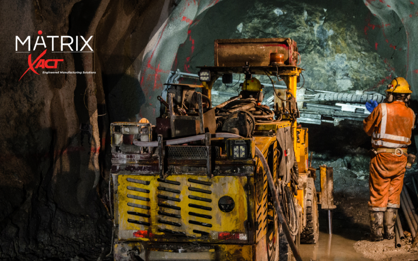
Northern Ontario’s underground mines operate in some of the most punishing conditions in Canada.

Between Sudbury’s deep hard-rock operations, Timmins’ gold mining corridors, and expanding electrified fleets across Ontario, mining equipment must withstand:

  • Sub-zero surface conditions
  • Moisture, slurry, and dust underground
  • Continuous vibration and shock
  • High-current electrification loads
  • Frequent rebuild and overhaul cycles

In these environments, cable assemblies do not fail because of “bad cable.”

They fail at interfaces, transitions, and integration points.

For mining OEMs and operators across Northern Ontario, reliability comes from engineered interconnect systems—custom cable assemblies designed for harsh underground service, electrified platforms, and repeatable rebuild programs.

Why Northern Ontario’s Underground Mines Demand Higher Interconnect Reliability

Underground mining in Ontario presents a unique combination of environmental stressors:

1. Sub-Zero Temperature Exposure

Surface equipment staging areas in Sudbury and Timmins regularly experience winter temperatures below -30°C. Equipment parked overnight, transported between sites, or deployed seasonally faces repeated cold-soak conditions.

Cold temperatures affect:

  • Jacket flexibility
  • Strain relief transitions
  • Overmold materials
  • Seal compression
  • Connector engagement force

Improperly engineered assemblies can stiffen, crack, or lose sealing integrity during freeze/thaw cycles.

2. Electrification of Underground Fleets in Ontario

Battery-electric mining equipment is expanding rapidly across Northern Ontario. Underground BEV haul trucks, loaders, and drilling platforms introduce new interconnect demands:

  • High-current power distribution
  • Mixed power + signal harnessing
  • Thermal cycling at connection points
  • High-voltage routing constraints
  • Increased vibration due to torque characteristics

High-current cable assemblies must manage:

  • Conductor sizing for duty cycle
  • Termination workmanship
  • Heat dissipation at contact interfaces
  • Mechanical protection in confined routing paths

Custom-engineered harnesses are critical to supporting fleet electrification while maintaining uptime.

Learn more about our approach to engineered builds at: Custom Cable Assemblies

Common Harness Failure Modes in Ontario Mining Equipment

In Northern Ontario mining operations, interconnect failures are predictable. They typically occur in six areas.

1. Cold-Induced Brittleness at Transition Points

At -30°C and below, materials behave differently.

Failures often originate at:

  • Connector backshell exits
  • Strain relief interfaces
  • Overmold-to-jacket transitions
  • Branch breakouts in multi-leg harnesses

Engineering Countermeasures:

  • Low-temperature-rated insulation systems
  • Transition geometry designed for stress distribution
  • Targeted overmolding to reduce conductor flex concentration
  • Validation of materials for cold flex performance

Overmolding must be engineered for stress management—not just environmental sealing.

Explore our overmolded assemblies: Overmolded Cables

2. Freeze/Thaw Ingress Failures

Northern Ontario equipment frequently transitions between:

  • Cold outdoor air
  • Warmer underground environments
  • Washdown maintenance bays

This creates condensation cycles inside connectors and junction points.

Common causes:

  • Incomplete interface sealing
  • Improper grommet sizing
  • Poor backshell compression
  • Inconsistent assembly practices

Engineering Countermeasures:

  • Sealed and booted transitions
  • Controlled assembly torque processes
  • Environmental validation aligned with actual mining conditions

For harsh-environment solutions: Rugged and Harsh Environment Assembly Solutions

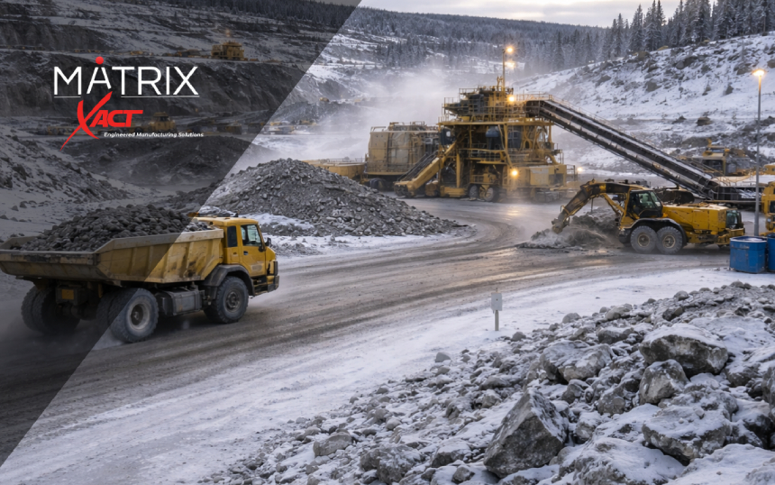
3. Abrasion and Mechanical Shock in Underground Routing

Underground mining equipment in Sudbury and Timmins operates in:

  • Tight tunnel geometries
  • Rock contact zones
  • High-vibration frames
  • Continuous motion environments

Abrasion damage typically occurs at:

  • Frame pass-through points
  • Clamp edges
  • Articulating joints
  • Battery compartment interfaces

Engineering Countermeasures:

  • Abrasion-resistant sleeving
  • Controlled routing architecture
  • Strain brackets and mechanical support
  • Repeatable harness layout documentation

Protective sleeving integration options: Tubing and Sleeving

4. High-Current Termination Overheating

Electrified fleets increase current density at:

  • Power connectors
  • Junction modules
  • Battery interface points

Improper crimping, insufficient conductor sizing, or poor contact selection can lead to:

  • Thermal buildup
  • Insulation degradation
  • Premature connector failure

Engineering Countermeasures:

  • Verified crimp tooling and pull testing
  • Conductor sizing aligned to real duty cycles
  • High-current-rated connector systems
  • Thermal-aware harness routing

5. Configuration Drift in Rebuild Programs

Mining fleets in Northern Ontario often operate for decades. Rebuild programs in Sudbury and Timmins require:

  • Harness replacement kits
  • Obsolescence management
  • Accurate documentation
  • Repeatable build quality

Common issues include:

  • Revision mismatch
  • Labeling inconsistencies
  • Substitution without traceability
  • Field-fit variations

Engineering Countermeasures:

  • Controlled documentation discipline
  • Revision-managed drawings
  • Serialized build tracking
  • Kitted harness solutions for depot deployment

XACT supports lifecycle programs through: Cable Repair & Recertification

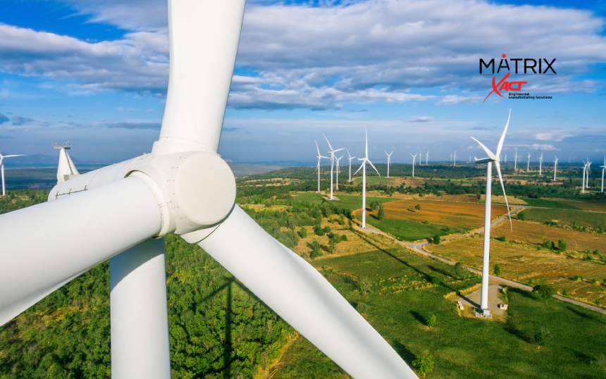
Electrification Trends in Sudbury and Timmins

Mining operators across Northern Ontario are accelerating:

  • Underground battery-electric fleet deployments
  • Ventilation efficiency upgrades
  • Automation and remote monitoring systems
  • Smart sensor integration

These trends increase:

  • Signal density
  • EMI exposure
  • High-current integration complexity
  • Connector interface counts

Cable assemblies are no longer passive components.

They are active contributors to platform reliability.

In electrified equipment, a harness failure can immobilize an entire unit—impacting production and increasing downtime costs.

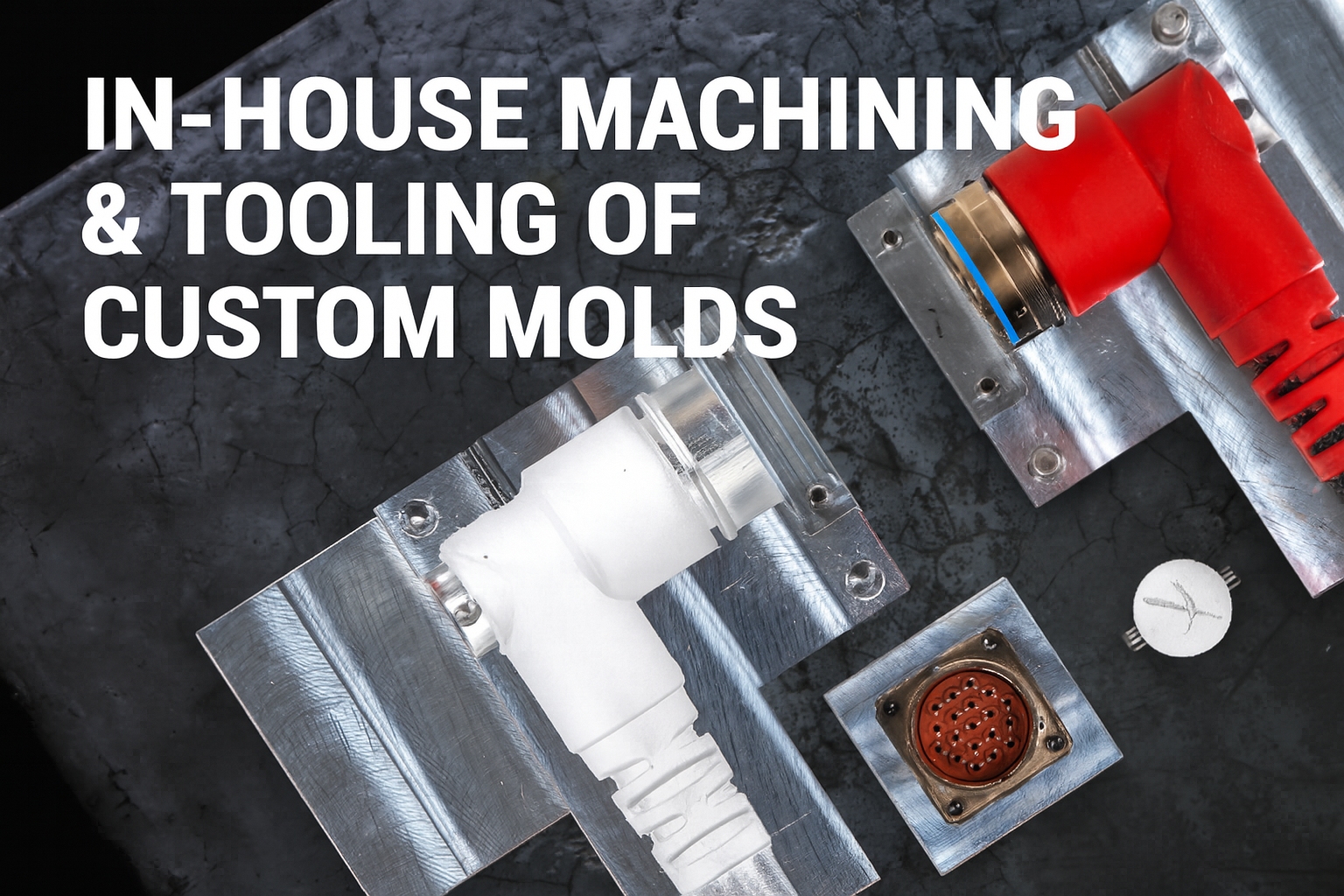
Designing Custom Cable Assemblies for Canadian Mining Conditions

Engineering for Northern Ontario requires accounting for:

  • -40°C surface exposure
  • Underground humidity
  • Abrasive particulate
  • Mechanical shock
  • Continuous duty cycles

Effective mining interconnect design integrates:

  • Strain management
  • Environmental sealing
  • High-current validation
  • Abrasion protection
  • Controlled documentation

The difference between commodity cabling and engineered assemblies is lifecycle thinking.

Custom cable assemblies designed for Canadian mining conditions support:

  • Extended service intervals
  • Reduced troubleshooting cycles
  • Faster rebuild turnaround
  • Improved mean time between failures (MTBF)

Partnering with Mining OEMs and Operators Across Ontario

Mining equipment OEMs, rebuild depots, and operators across Northern Ontario require partners who understand:

  • Platform qualification
  • Electrification complexity
  • Harsh underground routing constraints
  • Repeatable harness kit programs
  • Canadian environmental realities

Rugged cable assemblies are not simply selected—they are engineered around equipment geometry, duty cycle, and long-term sustainment strategy.

In Sudbury, Timmins, Thunder Bay, and across Ontario’s mining corridor, uptime depends on interconnect reliability.

Engineering for Uptime in Northern Ontario Mining

Sub-zero temperatures, vibration, moisture, and electrification loads are not edge cases in Northern Ontario—they are baseline conditions.

Cable assemblies designed without full-system consideration will eventually fail at their weakest interface.

Mining platforms reward disciplined engineering and lifecycle support.

They punish shortcuts.

When cold-weather performance, abrasion resistance, high-current integration, and documentation control are engineered into the harness architecture from the beginning, downtime decreases and fleet reliability improves.

Building or rebuilding underground mining equipment in Northern Ontario?

Talk to XACT’s engineering team about custom rugged cable assemblies, high-current harness systems, and repeatable rebuild kits designed for Canadian mining environments.

Surface and underground mining operations may extract similar materials, but the electrical environments they create are fundamentally different. From regulatory requirements to mechanical stress profiles, interconnect systems must be engineered differently depending on where they operate.

Designing cable assemblies, harnesses, and terminations without accounting for these differences increases the risk of premature failure, MSHA citations, and avoidable downtime. The most reliable mining programs treat surface and underground interconnect systems as distinct engineering challenges—each with its own compliance framework, environmental exposures, and dominant failure modes.

Regulatory Differences: Coal vs Metal/Nonmetal, Surface vs Underground

Electrical compliance in mining is governed primarily by the Mine Safety and Health Administration (MSHA). Requirements differ based on mine type and location.

Underground Coal Mines (30 CFR Part 75)

Underground coal operations face:

  • Strict flame-resistance requirements
  • Emphasis on trailing cable protection
  • Increased scrutiny on permissibility and ignition risk
  • Higher inspection sensitivity to damaged insulation or splices

Fire propagation risk in confined environments drives many of these requirements. Cable systems must limit flame spread and maintain grounding integrity under wet, abrasive conditions.

Surface Coal Mines (30 CFR Part 77)

Surface coal operations focus on:

  • Protection against physical damage
  • Grounding and bonding integrity
  • Guarding of energized conductors
  • Safe temporary power installations

Flame spread remains important, but open-air conditions reduce confinement risk.

Metal and Nonmetal Mines (30 CFR Parts 56 and 57)

Metal and nonmetal operations emphasize:

  • Protection from mechanical damage
  • Proper insulation and guarding
  • Ground-fault protection
  • Maintenance of wiring in crushers, conveyors, and process plants

The regulatory framework alone justifies differentiated interconnect strategies between underground and surface environments.

Mechanical Stress Profiles: Confined Flex vs Open-Site Impact

Underground Mining: High Flex + High Moisture

Underground interconnect systems are exposed to:

  • Continuous flexing in trailing cables
  • Sharp bend radii in confined routing paths
  • Constant moisture and water ingress risk
  • Rock abrasion and falling debris
  • Frequent machine movement and cable dragging

Common underground equipment includes:

  • Continuous miners
  • Shuttle cars
  • Load-haul-dump (LHD) vehicles
  • Bolters and drills

Trailing cables and high-flex harnessing are dominant architectures. Mechanical fatigue at termination points is one of the most frequent failure sources.

Engineering controls typically include:

  • High-strand-count conductors for flex endurance
  • Molded strain relief to prevent conductor breakage
  • Abrasion-resistant jacketing
  • Sealed or overmolded transitions at connectors

For assemblies designed specifically for these environments, see:

Rugged and Harsh Environment Assembly Solutions

Surface Mining: Impact, UV, and Vehicle Interaction

Surface mining introduces different mechanical risks:

  • UV degradation
  • Freeze-thaw cycling
  • Long cable runs exposed to vehicle traffic
  • Crushing risk from haul trucks and loaders
  • Steel structure abrasion
  • Dust contamination

Cable runs are often longer and more semi-permanent. While flex demands may be lower than underground trailing cables, exposure to environmental degradation is significantly higher.

Surface design priorities often include:

  • UV-resistant jacket materials
  • Crush protection or armored routing
  • Controlled strain relief at panel and junction transitions
  • Protective tubing and sleeving

Protective options include:

Tubing & Sleeving Solutions

Electrical Risk Differences

Underground Electrical Risk Profile

  • High humidity increases leakage current risk
  • Ground-fault sensitivity is critical
  • Flame propagation risk in confined airspace
  • Greater inspection scrutiny on damaged insulation

Failure of grounding continuity is especially serious underground. Proper termination practices and robust connector systems are essential.

Where high-current power interfaces are involved, properly engineered terminations and sealed strain relief are critical.

See: Overmolded Cable Assemblies

Surface Electrical Risk Profile

  • Voltage drop concerns over long distribution runs
  • Environmental degradation of insulation
  • Contamination of connectors from dust and mud
  • Intermittent grounding failures due to corrosion

Surface systems often incorporate larger distribution assemblies, portable substations, and panelized power systems.Termination integrity and environmental sealing remain critical but are stressed differently than underground.

Dominant Failure Modes by Environment

Environment Most Common Failure Drivers Typical Root Cause
Underground Conductor fatigue Repeated flex at machine interface
Underground Jacket breach Dragging on rock or steel edges
Underground Moisture ingress Inadequate sealing at terminations
Surface UV cracking Prolonged sunlight exposure
Surface Crushing damage Vehicle traffic over cable runs
Surface Connector contamination Dust and mud ingress

Recognizing these patterns allows interconnect systems to be engineered proactively rather than reactively.

Architecture Differences: Trailing Cable vs Distributed Assemblies

Underground Architecture

  • High-flex trailing cable systems
  • Frequent disconnect/reconnect cycles
  • Compact routing through confined machine frames
  • Greater reliance on molded breakouts and sealed interfaces

Hybrid power + control harnessing is common in mobile underground equipment.

See: Hybrid Cable Solutions

Surface Architecture

  • Longer, semi-permanent runs
  • Panel-to-equipment distribution
  • Greater emphasis on modular skids and junction boxes
  • Lower flex frequency but higher exposure risk

Surface processing plants introduce additional fixed harness and panel wiring assemblies.

Compliance Is a Lifecycle Issue, Not an Installation Event

Both surface and underground environments share one reality:

Electrical systems that are compliant on day one can become non-compliant through wear, damage, or field modification.

Effective compliance strategy includes:

  • Inspection intervals matched to environment severity
  • Controlled repair procedures
  • Documented rebuild and recertification programs
  • Traceable harness assemblies built to defined workmanship standards

For lifecycle support:

Cable Repair & Recertification

Engineering Implications for Mining Interconnect Design

Designing the same cable assembly for both surface and underground use without modification introduces unnecessary risk.

Instead, specification should consider:

  • Flex cycle requirements
  • Flame-resistance expectations
  • Environmental exposure (UV vs moisture dominance)
  • Routing method (dragging vs fixed support)
  • Inspection cadence
  • Termination access and strain relief design

When these variables are defined early, interconnect systems become predictable and durable rather than reactive maintenance items.

For full custom interconnect development:

Custom Cable Assemblies

Engineering the Right Interconnect for the Right Mine

Surface and underground mining may operate under the same regulatory umbrella, but they impose fundamentally different electrical and mechanical demands. The most reliable programs treat these environments separately during specification, validation, and maintenance planning.

Engineering cable assemblies to match real environmental stress—rather than defaulting to generic “mining-rated” solutions—reduces citation risk, improves uptime, and extends service life across the fleet.

Wind turbines operate under constant mechanical stress. Inside the tower and nacelle, cable systems are exposed to vibration, torsional movement, temperature cycling, moisture, oils, and tight routing constraints. When interconnect systems fail, the result is downtime, costly mobilization, and extended troubleshooting cycles.

Reliable turbine performance starts with cable assemblies engineered specifically for motion, environmental exposure, and long-term serviceability.

Below are practical best practices for OEMs and service teams focused on improving reliability and reducing lifecycle cost.

Design for Motion: Vibration, Flexing & Rotation

Wind turbines are dynamic systems. Yaw rotation, pitch adjustments, and nacelle vibration all place continuous strain on cable assemblies.

Assemblies designed for static environments will fail prematurely in rotating systems.

Best practices:

  • Engineer for torsional stress in yaw loops
  • Maintain proper bend radius under continuous flex
  • Reinforce connector transitions with strain relief
  • Select jacket materials suited to UV, cold temperatures, and chemical exposure
  • Avoid compression damage from rigid mounting methods

XACT manufactures overmolded cable assemblies that reinforce connector transitions, improve environmental sealing, and extend service life in high-vibration applications.

Learn more about Overmolded Cable Assemblies

For extreme-duty applications:

Explore Rugged & Harsh Environment Cable Assemblies

Route Cables Strategically Around Turbine Components

Routing directly impacts durability. Poor routing increases abrasion, compression stress, and thermal exposure.

Standardizing routing design reduces variability between builds and simplifies field service.

Smart routing guidelines:

  • Avoid sharp edges and abrasion points
  • Use cushioned clamps without over-tightening
  • Maintain clearance from moving mechanical systems
  • Keep assemblies away from high-heat components
  • Design routing paths consistently across turbine platforms

For multi-branch harness distribution, molded breakouts provide organization and improved strain control.

View Molded Breakout & Splitter Solutions

Reduce Tower Time with Field-Ready Assemblies

Every hour inside a turbine increases operational cost. Serviceability must be considered during design, not after deployment.

Service-focused strategies:

  • Use pre-terminated harness assemblies
  • Standardize modular replacement kits
  • Minimize field termination requirements
  • Incorporate clear identification for fast troubleshooting
  • Design assemblies for glove-friendly handling

When refurbishing or extending the life of existing assemblies is more practical than replacement, XACT supports repair and recertification programs.

Cable Repair & Recertification Services

Protect Against Environmental Exposure

Wind installations encounter:

  • Extreme cold and heat cycling
  • Moisture and condensation
  • Salt exposure in coastal sites
  • Dust and particulate contamination
  • Oil and chemical exposure inside nacelles

Environmental sealing and mechanical protection are essential for maintaining signal integrity and power reliability.

Protective enhancements may include:

  • Environmental overmolding at transition points
  • Heat shrink tubing for insulation and strain relief
  • PTFE tubing for chemical and temperature resistance
  • Abrasion-resistant sleeving in high-contact zones

Heat Shrink Tubing Solutions

PTFE Tubing Solutions

Tubing & Sleeving Solutions

Maintain Signal Integrity in High-Power Environments

Wind turbines combine high-power systems with sensitive control and communication networks. EMI, contamination, and mechanical degradation can lead to intermittent faults and unexpected shutdowns.

Shielding, braiding, and reinforced terminations help preserve signal performance in electrically noisy environments.

EMI & Metal Braiding Solutions

Engineer for Lifecycle Reliability

Effective cable management extends beyond initial installation. Long-term performance depends on documentation control, manufacturing consistency, and supply chain stability.

XACT supports energy OEMs with:

  • Custom cable assemblies built to specification
  • Integrated electromechanical builds
  • Engineering design collaboration
  • Controlled manufacturing processes
  • Program-level supply chain support

Engineering Design Services

Energy Sector Solutions

Wind turbine uptime depends heavily on the integrity of its interconnect systems. Designing for motion, protecting against environmental hazards, standardizing routing, and simplifying field service significantly reduces failure risk.

Whether supporting new turbine platforms or upgrading existing fleets, engineered cable assemblies built for harsh wind environments deliver measurable improvements in reliability and service efficiency.

Electric fracturing (“e-frac”) reduces diesel equipment on location, but it increases the amount of electrical power and operational data moving through the spread. That combination raises the stakes for cables, connectors, and harnesses: more current, more heat, more EMI exposure, and more failure risk from abrasion, fluids, and repeated handling. The most reliable e-frac systems treat interconnects as engineered subsystems—defined by conductor sizing and termination quality, robust strain relief/overmolding, shielding and sealing strategy, and validation testing that reflects real frac duty cycles.

Why E-Frac Changes the Interconnect Problem

E-frac and modern frac automation shift the interconnect requirement from “durable cabling” to “power + controls + data infrastructure” that must perform under:

  • High continuous and transient current loads (including motor starts and dynamic load profiles)
  • Long cable runs with voltage drop constraints
  • Harsh EMI environments (VFDs, power electronics, switching transients, radio systems)
  • Abrasion, impact, and repeated handling during rig-up/rig-down
  • Fluid exposure (water, hydraulic fluids, fuels, chemicals) and wide thermal swings
  • Time-critical uptime requirements, where a single interconnect fault can halt a stage

The outcome is predictable: interconnects become a reliability limiter unless they’re designed and validated like any other mission-critical subsystem.

Architecture Overview: What “Connectivity” Looks Like on an E-Frac Spread

While spread architectures vary by OEM and operator preferences, most e-frac deployments concentrate interconnect risk into a few system types:

High-Power Distribution

  • High-current feeder cables and power distribution assemblies
  • Connectors and terminations exposed to dirt, moisture, and rough handling
  • Junction/transition points with recurring connect/disconnect cycles

Control + Instrumentation Harnessing

  • Harnesses for sensors, actuators, safety circuits, and interlocks
  • Cable routing near vibration sources and pinch points
  • Interfaces that must remain stable under movement and service events

Data Connectivity for Automation

  • Industrial Ethernet or fieldbus segments, sensor/telemetry cabling, and mixed-signal harnessing
  • Noise immunity requirements due to nearby high-energy switching
  • Connector reliability and shield termination consistency that directly impact signal integrity

Hybrid Interconnects (Power + Signal in One Assembly)

Hybrid assemblies are increasingly used to reduce routing complexity and speed rig-up, but they demand careful design to prevent coupling noise into signal conductors and to manage thermal and mechanical stress.

For mixed assemblies, see XACT’s Hybrid Cable Solutions page for typical construction patterns and application examples: hybrid cable solutions.

Common Failure Modes in Frac Interconnect Systems (and What Prevents Them)

Interconnect failures in frac environments tend to cluster into repeatable categories. The value is not “knowing they happen,” but designing out the root causes.

Quick Reference Table: Failure Modes vs Engineering Controls

Failure Mode Typical Root Cause Engineering Control Validation / Test Focus
Conductor strand break / open circuit Flexing at termination, poor strain relief, repeated handling Molded strain relief, controlled bend radius, proper conductor selection Flex / pull / strain-relief verification
Intermittent signal / comm drop Shield termination inconsistency, connector micro-motion, EMI coupling Proper shield bonding, braided shielding, connector retention, routing separation Continuity under vibration; EMI performance checks
Overheating at termination Undersized conductors, high contact resistance, poor termination process Correct conductor sizing, crimp/termination process control, contact selection Temperature rise checks; insulation resistance; hipot (as applicable)
Water/fluid ingress Inadequate sealing, damaged boots, wicking along conductors Overmolding, sealed connector interfaces, potting where needed Ingress testing; thermal cycling + exposure
Abrasion jacket failure Dragging, pinch points, cable-on-metal contact Protective sleeving/tubing, abrasion-resistant jacketing, routing hardware Abrasion evaluation; field handling simulation
Connector damage during service Mis-mating, side loading, poor protection during transport Keyed interfaces, protective caps, service-friendly mechanical design Repeated mate/de-mate; handling trials

For harsh-environment builds designed around these failure modes, see: rugged and harsh environment assembly solutions.

Engineering Considerations That Matter in E-Frac

1) High-Current Design: It’s Not Only Ampacity

E-frac power assemblies must withstand real-world thermal and mechanical conditions—not just meet a nominal current rating.

Key considerations:

  • Conductor selection and stranding optimized for flexing and handling
  • Contact resistance control through consistent termination processes
  • Thermal management at terminations (hot spots often occur at interfaces)
  • Voltage drop and long-run performance, especially where power distribution topology is modular

Where appropriate, assemblies should be validated with electrical tests that reflect duty cycles and thermal rise under expected loads (not only room-temperature bench checks).

2) Strain Relief + Overmolding: Designing for Handling, Not Just Operation

Frac locations are hard on interconnects during transport, rig-up/rig-down, and troubleshooting. Overmolding and molded strain relief can reduce the primary causes of field failures by:

  • Controlling bend radius at transitions
  • Stabilizing conductor terminations
  • Adding mechanical protection at high-stress points
  • Improving environmental sealing at interfaces

Relevant solution area: overmolded cable assemblies and molded breakout or splitter solutions.

3) EMI in Power-Electronics-Dense Environments

E-frac increases the density of switching electronics and high-current routing, which raises EMI exposure. That EMI can affect:

  • Sensor signal fidelity
  • Control system stability
  • Data communication robustness
  • Diagnostic accuracy (especially where predictive maintenance is deployed)

Engineering controls typically include:

  • Shield design appropriate to frequency content (braid coverage, drain strategy, bonding)
  • Separation of power and signal paths (and controlled crossing techniques)
  • Connector interface practices that preserve shield continuity
  • Grounding strategy alignment with the equipment’s architecture

Relevant solution area: EMI and metal braiding solutions.

4) Environmental Protection: Fluids, Abrasion, and Thermal Cycling

Frac interconnects are exposed to water, oil, hydraulic fluids, sand/dust, UV, and aggressive handling. Design choices that help:

  • Jacket materials and protective sleeving selected for abrasion and chemical exposure
  • Sealed transitions and end treatments that prevent wicking and ingress
  • Heat-shrink and boot systems designed for mechanical stability and sealing

Relevant solution areas: tubing & sleeving, heat shrink tubing solutions, and PTFE tubing solutions.

5) Documentation Discipline and Build Consistency

Automation and electrification programs tend to standardize. Standardization increases the value of:

  • Revision control and repeatable manufacturing
  • Test records and traceability expectations
  • Controlled workmanship practices for harness builds

A common workmanship reference used across many harness programs is IPC/WHMA-A-620 (acceptability of cable and wire harness assemblies). Whether or not a program specifies it explicitly, the underlying principle remains: consistent processes reduce variability that becomes downtime.

For quality and compliance context, refer to: certificates & accreditations.

Field Service Reality: Why Repair and Recertification Matter

Even well-designed frac interconnect systems face damage events: pinch points, vehicle passes, hurried rig-down, unexpected exposure, or legacy assemblies that no longer have OEM support.

A structured MRO approach typically includes:

  • Failure triage and root cause assessment
  • Rebuild-to-spec with controlled materials and termination processes
  • Verification testing (electrical + mechanical; environmental as needed)
  • Documentation to support ongoing fleet reliability programs

For lifecycle support programs, see: cable repair & recertification.

Practical Guidelines for Specifying E-Frac Interconnects

If you’re defining or revising interconnect requirements for an electrified/automated frac spread, these questions surface the real design constraints:

Electrical

  • What are continuous and transient current requirements by duty cycle?
  • What voltage drop constraints exist across typical run lengths?
  • What insulation resistance and hipot requirements apply (if any) for the system voltage class?

Mechanical / Handling

  • How many connect/disconnect cycles are expected per season?
  • Where are the known bend points, pinch points, and abrasion zones?
  • What pull/strain conditions occur during rig-up/rig-down?

Environmental

  • What fluids and chemicals will assemblies contact?
  • What temperature range and thermal cycling profile is expected?
  • What ingress protection level is required at interfaces?

Controls / Data

  • What noise immunity is required for control and sensor harnesses?
  • How is shield continuity managed across connectors and junctions?
  • What is the grounding strategy and how will it be enforced during assembly?

When the answers are unclear, engineering-first prototyping and validation is usually the fastest path to a stable spec.

For co-engineering support, see: engineering design services.

E-frac and intelligent automation increase the value—and the risk—of interconnect systems. Reliability improvements come from treating cables, connectors, and harnesses as engineered subsystems with defined mechanical, electrical, EMI, and environmental requirements.

The strongest frac interconnect programs are built around:

  • High-current design validated by real duty cycles
  • Robust strain relief and environmental sealing (often via overmolding)
  • EMI controls aligned to power-electronics realities
  • Protective sleeving/tubing matched to abrasion and chemical exposure
  • Documentation and repeatable build/testing practices
  • A repair/recert pathway that supports fleet uptime

At the heart of the global energy capital, XACT’s Houston Facility stands as a premier destination for custom cable assembly and overmolded cable solutions—engineered specifically for the rugged demands of the oil and gas industry.

Watch the video tour here: https://xactusa.com/facility/

Purpose-Built for Performance in Houston

Strategically located to serve Houston’s critical upstream and downstream sectors, the XACT Houston Facility combines cutting-edge manufacturing capabilities with deep domain expertise in energy applications. Our in-house engineering and production teams specialize in:

  • Custom cable assembly for high-vibration, high-temperature, and corrosive environments
  • Overmolded cable systems with robust mechanical protection and long-term sealing performance
  • Short lead times and responsive support tailored to the fast-paced needs of Houston’s oilfield service and equipment companies

Certified Quality. Built in America. Trusted Worldwide.

XACT proudly designs, builds, and tests its cable assemblies right here in the USA. The Houston team operates in a quality-driven environment, holding industry-leading certifications that guarantee product integrity and compliance in the most demanding markets:

  • ISO 9001:2015 – Quality Management
  • ISO 13485:2016 – Medical Device Quality
  • ITAR Registered – U.S. Export Control Compliance
  • UL & CSA Certifications – North American Safety Standards
  • IPC/WHMA-A-620 Certified Workforce – Wiring Harness Assembly Excellence

For the full list of credentials, visit our certifications page: https://xactusa.com/certification-accreditations/

Built for the Field. Backed by Experience.

With decades of expertise supporting the Houston energy sector, XACT delivers more than cables—we deliver performance, protection, and peace of mind. Whether your application demands high-pressure downhole durability or surface instrumentation reliability, our American-made solutions are ready to go to work.

Ready to talk cable assemblies that work as hard as your tools do?

Visit us at xactusa.com or schedule a tour of our Houston Facility here.