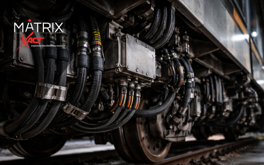
Modern military ground vehicles are no longer purely mechanical systems. Today’s wheeled combat vehicles, armored personnel carriers, tactical support trucks, and missionized shelters integrate mission computers, tactical radios, remote weapon stations, CANBUS/J1939 networks, power distribution units, high-speed data systems, and RF communications.

As vehicle digitization expands, so does the complexity of vetronics cable assemblies that connect these subsystems.

Explore Military-Grade Cable Assemblies:

In high-vibration, EMI-dense military environments, harness protection is not cosmetic — it is mission-critical. This article explains where military vehicle wire harnesses fail and how shielding, tubing, sleeving, and molded transitions are engineered into rugged cable assemblies to reduce intermittent faults and improve long-term sustainment outcomes.

Why Vetronics Cable Assemblies Fail in Military Ground Vehicles

Ground vehicle environments create predictable failure modes. Most issues trace back to routing mechanics, transition design, shielding integrity, and environmental exposure — not “bad cable.”

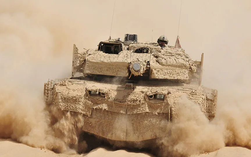
High Vibration and Shock Fatigue

Off-road military vehicles experience continuous vibration, torsional stress, and repeated shock loading. Failures often initiate at:

  • Connector exits and backshell transitions
  • Molded breakout points
  • Unsupported spans near suspension or turret structures

Without proper strain relief and overmolding — such as those used in overmolded cable assemblies — conductors and shield layers can fatigue over time, leading to intermittent faults that are extremely difficult to diagnose in the field.

Abrasion and Chafing in Armored Chassis

Routing through armored hulls, bulkheads, turret rings, and articulated joints introduces:

  • Metal edges
  • Clamp pressure points
  • Repetitive rubbing zones
  • Pinch hazards

Abrasion can damage outer jackets, braid shields, foil shields, and conductor insulation. Engineered tubing and sleeving systems play a critical role here. Protective solutions found under Tubing & Sleeving provide abrasion resistance and bundle stability in high-wear zones.

For shielding reinforcement, EMI and metal braiding solutions help protect signal integrity in vibration-heavy environments.

EMI and Signal Integrity Risk in Vetronics Systems

Modern vetronics architecture combines:
  • High-current power distribution
  • Shielded twisted pair networks
  • CANBUS / J1939 communication lines
  • Ethernet and high-speed data links
  • RF coax assemblies

Improper shielding or damaged braid/foil layers increase susceptibility to electromagnetic interference (EMI), potentially disrupting mission-critical systems.

Effective EMI control may incorporate:

  • Shielded harness constructions
  • Controlled impedance requirements
  • RF assemblies
  • Shielded and filtered connectors
  • Enclosure-level EMI sealing solutions

For broader EMI containment at the enclosure level, shielded gasket solutions and EMI foil tape solutions can support system-level shielding continuity.

The goal is not maximum shielding — it is correct shielding architecture, properly terminated and mechanically protected.

Environmental Exposure on External Harnesses

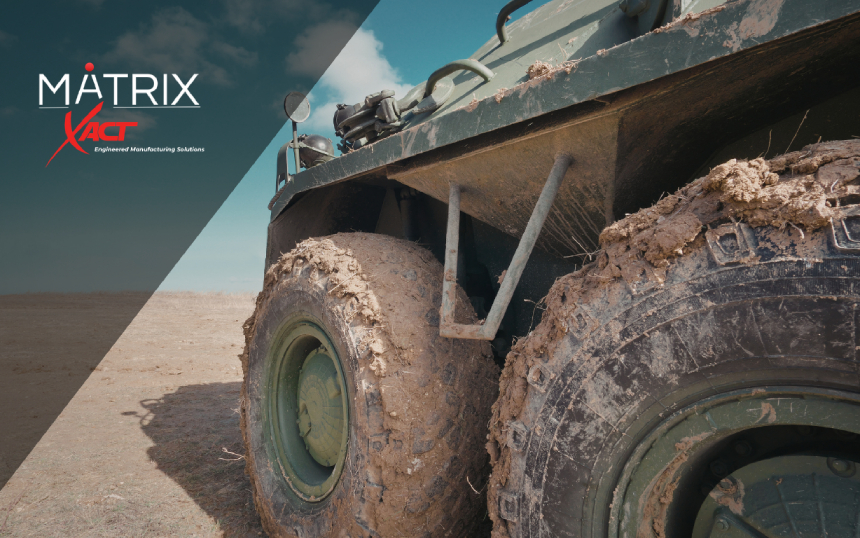
External harnesses on military ground vehicles are exposed to:

  • Fuel, oil, and hydraulic fluids
  • Dust and debris
  • Washdown conditions
  • UV radiation
  • Extreme temperature cycling

Material selection must align with real exposure profiles. Common protective solutions include:

Engineering Rugged Military Vehicle Wire Harnesses

A rugged military vehicle wire harness integrates mechanical protection, EMI control, and configuration discipline into a controlled build.

Tubing and Sleeving as Engineered Protection Systems

Protective sleeving supports:
  • Abrasion resistance
  • Cut-through protection
  • Bundle organization
  • Breakout reinforcement
  • Thermal and chemical protection

Material attributes commonly specified in defense programs include abrasion resistance, chemical resistance, high flex capability, UV resistance, flame retardance, and compliance-driven material constraints.

Tubing and sleeving are not standalone accessories — they function as part of a rugged harness system designed to survive long-term vibration and environmental stress.

Molded Breakouts and Transition Protection

High-stress areas require reinforcement. Molded breakout or splitter solutions are frequently used at:
  • Connector exits
  • T-type splits
  • Y-type splits
  • X-type branch transitions

These molded transitions improve strain relief, protect shield terminations, and reduce conductor fatigue under dynamic loading.

Hybrid Power + Signal Assemblies

Military ground vehicles increasingly use hybrid cable assemblies combining:

  • Power conductors
  • Control signals
  • Data networks
  • RF interfaces

Hybrid cable solutions reduce connection points and simplify routing, but they require disciplined segregation and shielding to prevent cross-coupling and signal degradation.

External vs. Internal Harness Protection

Harness External (Exposed Routing)

External harnesses typically require:

  • Abrasion-resistant sleeving
  • Environmental sealing
  • Chemical-resistant materials
  • Booted or heat-shrink transitions

These often align with rugged and harsh environment assembly solutions.

Harness Internal (Protected Electronics Bays)

Internal harnesses often prioritize:

  • Shield integrity
  • Signal integrity / impedance control
  • Clean breakout geometry
  • Configuration management and documentation
Engineering support through engineering design services can help align mechanical protection with electrical performance requirements.

Sustainment and Ground Vehicle Modernization

Military ground platforms remain in service for decades. That creates recurring demand for:
  • Replacement harnesses
  • Retrofit harness kits
  • Controlled rebuilds
  • Obsolescence-driven replacements
  • Repair and recertification
Cable repair and recertification services support sustainment programs where reliability and documentation accuracy are essential. Supply chain continuity through structured supply chain management also plays a key role in defense sustainment cycles.

Practical Takeaways for Vetronics Harness Protection

When evaluating rugged cable assemblies for military ground vehicles, focus on:
  • Where abrasion will occur and how it is mitigated
  • How transitions are strain-relieved and reinforced
  • How shielding is protected and terminated
  • How environmental exposure is addressed
  • How configuration control supports long-term sustainment
Ground vehicle modernization continues to increase electrical density, networking complexity, and EMI sensitivity. Harness protection — including tubing, sleeving, shielding, and molded transitions — directly impacts reliability, fleet readiness, and maintenance burden.

Rail platforms are designed for 30–40 years of service life.

Your cable assemblies are expected to survive every one of them.

Between high-vibration undercarriage routing, washdown exposure, traction power EMI, thermal cycling, and repeated maintenance handling, rail interconnect systems operate in conditions far more severe than most industrial environments. Yet once qualified, they are often locked into a platform for decades.

When harness failures occur, they rarely fail in isolation. They trigger troubleshooting cycles, service disruptions, parts obsolescence challenges, and—in signaling applications—potential safety exposure. In rolling stock programs, redesigning or requalifying an interconnect after platform release can be significantly more disruptive and expensive than engineering it correctly upfront.

For rail OEMs, signaling integrators, and depot MRO teams, reliability is not about selecting a “tough cable.” It is about engineering a custom cable assembly system that accounts for vibration, ingress, EMI, routing constraints, serviceability, and long-term configuration control from day one.

The most common rail interconnect failures are predictable. And when addressed at the design stage, they can be engineered out before they ever reach the field.

The 6 Most Common Rail Cable Assembly Failure Modes — and How to Engineer Them Out

1. Vibration Fatigue at Connector Transitions

The Problem

Rail vehicles and wayside systems experience:

  • Continuous vibration
  • Shock loading
  • Micro-movement at clamp points
  • High-frequency harmonics from traction systems

Failure typically initiates at:

  • Connector backshell exits
  • Strain relief transitions
  • Harness branch points
  • Rigid-to-flex transitions

Intermittent faults are often the first symptom—making diagnosis costly and time-consuming.

Engineering Solutions

  • Purpose-built strain relief geometry
  • Targeted overmolding at high-stress transitions
  • Branch design optimized for real routing constraints
  • Controlled termination processes to ensure repeatability
  • Mechanical support strategy integrated into harness design

Overmolding is particularly effective when engineered for stress distribution rather than cosmetic sealing.

Learn more about engineered transition protection in our Overmolded Cable Assemblies solutions.

2. Moisture Ingress and Connector Corrosion

The Problem

Rail systems are exposed to:

  • Washdown procedures
  • Outdoor weather
  • Condensation cycles
  • Road debris and splash zones

Ingress failures often originate not at the connector face, but at:

  • Cable-to-connector interfaces
  • Inadequate backshell sealing
  • Improper grommet sizing
  • Inconsistent assembly torque or potting

Engineering Solutions

  • Sealing the entire interface system—not just the connector
  • Booted or overmolded transition zones
  • Environmental validation aligned with real deployment conditions
  • Defined assembly controls for repeatability

For harsh-environment rail builds, see: Rugged and Harsh Environment Assembly Solutions.

3. Abrasion in Undercarriage and Wayside Routing

The Problem

Abrasion damage rarely occurs randomly. It is usually traceable to:

  • Frame pass-through points
  • Clamp edges
  • Vibration-driven rubbing
  • Maintenance handling

Over time, jacket wear exposes shielding and conductors.

Engineering Solutions

  • Abrasion-resistant sleeving in known contact zones
  • Strain brackets and routing control strategies
  • Protective transitions at bulkheads
  • Serviceability-focused harness layout

Protective sleeving and tubing options can be integrated directly into build specifications.

4. EMI and Signal Integrity Failures in Train Control Systems

The Problem

PTC, CBTC, TCMS, and signaling systems operate in high-EMI environments due to:

  • Traction power systems
  • High-current switching
  • Nearby RF communication equipment

Improper shielding termination or inconsistent grounding strategies can result in:

  • Data corruption
  • False fault indications
  • Reduced system reliability

Engineering Solutions

  • Defined shield termination architecture
  • Controlled 360° shield bonding where required
  • Ground strategy aligned to system integrator specifications
  • Low-noise cable assemblies built for signal integrity

See our experience in signal-focused builds within the Communications & Telecom Sector

5. Thermal Degradation at High-Current Interfaces

The Problem

High-current traction and auxiliary power systems generate localized heat at:

  • Crimp interfaces
  • Terminal blocks
  • Connector contacts

Improper termination or underspecified conductors can accelerate insulation breakdown and reduce service life.

Engineering Solutions

  • Correct conductor sizing for duty cycle
  • Crimp validation and pull-test documentation
  • Thermal-aware routing inside enclosures
  • High-current rated connectors and assemblies

XACT supports high-current and mixed power/signal harness builds through our Custom Cable Assemblies program.

6. Documentation and Configuration Drift Over Long Service Life

The Problem

Rail platforms evolve over decades. Without disciplined configuration control:

  • Harness revisions drift
  • Replacement builds mismatch
  • Labeling inconsistencies create service errors
  • Obsolescence introduces undocumented substitutions

This is one of the most common causes of depot frustration.

Engineering Solutions

  • Controlled drawings and revision management
  • Traceable build documentation
  • Test records retained for lifecycle support
  • Kitting strategies for MRO programs

For lifecycle extension and rebuild programs, explore: Cable Repair & Recertification

Rail-Specific Compliance Considerations

Depending on application lane, rail interconnect programs may require:

  • EN 45545 fire/smoke compliance (rolling stock)
  • AAR standards (freight)
  • Documented EMI/EMC awareness
  • Ingress protection validation
  • Long-term traceability and configuration discipline

Engineering for compliance must begin at the design stage—not after platform qualification.

Designing for the Rail Lifecycle

Rail interconnect reliability is not about preventing “cable damage.”

It is about designing:

  • For 30–40 year service life
  • For depot-level serviceability
  • For configuration control across program revisions
  • For environmental realities—not lab assumptions

The difference between commodity cable supply and engineered rail harness systems is lifecycle thinking.

When vibration, EMI, moisture, and thermal loads are accounted for at the architecture stage, failure rates drop, troubleshooting cycles shorten, and MRO operations stabilize.

Rail platforms reward disciplined engineering.

They punish shortcuts.

Ready to engineer failure-resistant cable assemblies for your rail platform?

Talk to XACT’s engineering team about custom harness design, rugged overmolding, high-current builds, and long-term MRO support.

XACT engineered a 100% shielded, field-repairable fuse holder for the U.S. Army’s M1 Abrams main battle tank. The redesigned assembly improved EMI protection, reduced field downtime, and enhanced mission readiness in harsh armored vehicle environments.

Program Overview

XACT Engineered Manufacturing Solutions was engaged to resolve a field reliability issue affecting electrical subsystems on the M1 Abrams main battle tank platform operated by the United States Army.

The challenge required a defense-grade redesign aligned with our Military-Grade Cable Assemblies capabilities, built for extreme vibration, shock, and electromagnetic interference conditions typical of armored vehicle platforms.

The Challenge

The U.S. Army was experiencing recurring performance issues with a field-repairable fuse holder used within the Abrams electrical architecture.

Key technical concerns included:

  • Insufficient EMI shielding
  • Exposure to high vibration and mechanical shock
  • Environmental durability limitations
  • Increased field service time
  • Reduced platform readiness

Electrical reliability in armored ground vehicles directly impacts operational availability. The fuse holder required redesign to improve shielding performance, durability, and field serviceability.

The Engineering Solution

Through a structured evaluation using our Engineering Design Services, XACT developed a redesigned, fully shielded, field-repairable fuse holder assembly optimized for military vehicle deployment.

The upgraded assembly incorporated:

  • 100% EMI shielding architecture
  • Ruggedized mechanical structure for vibration resistance
  • Field-repairable configuration to reduce downtime
  • IPC/WHMA-A-620 Class 3 workmanship standards
  • Full traceability and documentation support

Where additional electromagnetic mitigation strategies were required at the enclosure level, shielding continuity was supported through engineered material solutions such as Shielded Gasket Solutions, the EMI Shielding portfolio, EMI Foil Tape Solutions, and RF Absorbing Solutions.

This system-level integration ensures shielding effectiveness across both interconnect and enclosure interfaces.

Results

Following validation and evaluation, the United States Army approved and adopted the redesigned shielded fuse holder for integration into M1 Abrams platforms.

Program impact included:

  • Reduced field service downtime
  • Improved electrical reliability under combat vibration profiles
  • Increased mission readiness
  • Long-term deployment adoption

The solution remains in service today and reflects XACT’s capability to deliver ruggedized interconnect systems for mission-critical defense programs.

Defense Manufacturing Capabilities

This program reflects XACT’s broader expertise across:

Supporting production continuity through structured Supply Chain Management, integrated Value-Added Services, and precision Machining & Fabrication.

Compliance & Certifications

XACT supports controlled defense programs under AS9100D / ISO 9001 certification and IPC Class 3 workmanship standards.

Full compliance documentation is available on our Certificates & Accreditations page.

Our supply chain transparency policies can also be reviewed through our Conflict Minerals Statement.

Integrated Materials & Interconnect Strategy

Complex defense systems often require coordinated material and interconnect engineering.

Through our Integrated Interconnect & Cable Assembly Solutions approach, Matrix provides engineered EMI, thermal, sealing, and identification materials while XACT manufactures ruggedized cable assemblies, overmolds, connectors, and electromechanical builds.

This integrated structure reduces program risk and improves shielding, sealing, and overall system reliability.

Supporting Long-Life Defense Programs

Defense platforms demand long lifecycle support and production continuity. XACT provides:

  • Controlled documentation management
  • Secure engineering collaboration
  • Repair and refurbishment of fielded assets
  • Recertification for defense and regulated programs

For secure drawing submission or engineering consultation, visit our Contact page or explore our full Military-Grade Cable Assemblies capabilities.