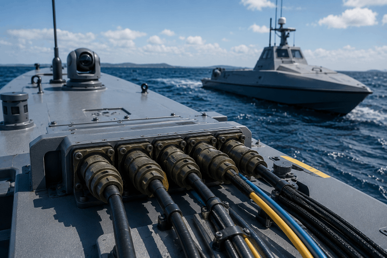
Unmanned surface vehicles (USVs) and unmanned underwater vehicles (UUVs) are increasingly being designed as adaptable platforms rather than single-purpose vessels. The same vehicle may need to support surveillance equipment, environmental sensors, sonar, communications systems or other mission-specific payloads at different points in its operational life.
That flexibility depends on more than software and interchangeable equipment bays. It also requires an electrical infrastructure capable of supplying the appropriate power, data, RF and control connections whenever the payload changes.
A fixed wiring design may work well for the original configuration but become a constraint when new sensors require additional bandwidth, different connectors, greater power or improved electromagnetic interference protection.
Modular cable architectures help autonomous maritime programs prepare for those changes by treating cable assemblies and wire harnesses as part of the platform architecture—not as components selected after the rest of the design is complete.
The Platform and Its Electronics Operate on Different Lifecycles
The physical structure of an autonomous vessel represents a major long-term investment. Its hull, propulsion system, buoyancy, structural components and mechanical layout are developed around demanding performance and environmental requirements.
Mission electronics typically evolve much faster.
Sonar, radar, EO/IR equipment, satellite communications, autonomy processors, navigation hardware and onboard networking technologies are continually improving. Operational needs can also change before the vessel reaches the end of its useful life.
A platform may therefore remain structurally capable while its original electronics become insufficient for newer missions.
When the interconnect system is hardwired around one generation of equipment, integrating an upgraded payload may require:
- Pulling new cable through the vessel
- Reworking internal wire harnesses
- Replacing bulkhead interfaces
- Adding adapters or transition assemblies
- Modifying power distribution
- Requalifying portions of the electrical system
- Updating drawings, bills of materials and maintenance procedures
These changes can introduce cost, schedule risk and new potential failure points.
A modular cable architecture separates the durable platform from the equipment most likely to change. Standardized connection points, replaceable harness segments and scalable power and data pathways allow the vessel to accommodate new capabilities without redesigning its entire electrical backbone.
Why Autonomous Maritime Payloads Change So Frequently
Autonomous maritime platforms are often expected to support multiple mission profiles.
Depending on the vessel and operator, those missions may include:
- Intelligence, surveillance and reconnaissance
- Hydrographic surveying
- Mine detection or countermeasure operations
- Environmental monitoring
- Offshore infrastructure inspection
- Maritime domain awareness
- Acoustic data collection
- Communications relay
- Search and recovery
- Scientific research
Each mission can require a different combination of sensors, antennas, processing hardware and communications equipment.
Even when the mission remains the same, the supporting technology may change. A new sensor might generate more data, require a different voltage, use another communication protocol or place greater demands on the platform’s RF and electromagnetic compatibility strategy.
The cable architecture must therefore support more than the payload installed today. It should also consider how the interface may need to change when that payload is upgraded, replaced or combined with additional equipment.
What Is a Modular Cable Architecture?
A modular cable architecture divides the platform’s interconnect system into defined, serviceable sections connected through repeatable interfaces.
Instead of running a unique point-to-point cable for every device, the platform may use common trunks, distribution harnesses, bulkhead connections and payload-specific assemblies.
A typical architecture may include:
- A primary power and data backbone
- Internal power and signal wire harnesses
- Bulkhead or panel-mounted connection points
- Replaceable payload harnesses
- RF and antenna cable assemblies
- Hybrid assemblies carrying multiple functions
- Short transition assemblies between standardized and payload-specific interfaces
- Labeled, keyed or color-coded connections for field installation
The objective is not to eliminate customization. Autonomous vessels frequently require highly application-specific assemblies.
The objective is to contain that customization within manageable modules. When a payload changes, engineers can replace or revise the relevant cable segment rather than disturbing the full platform harness.
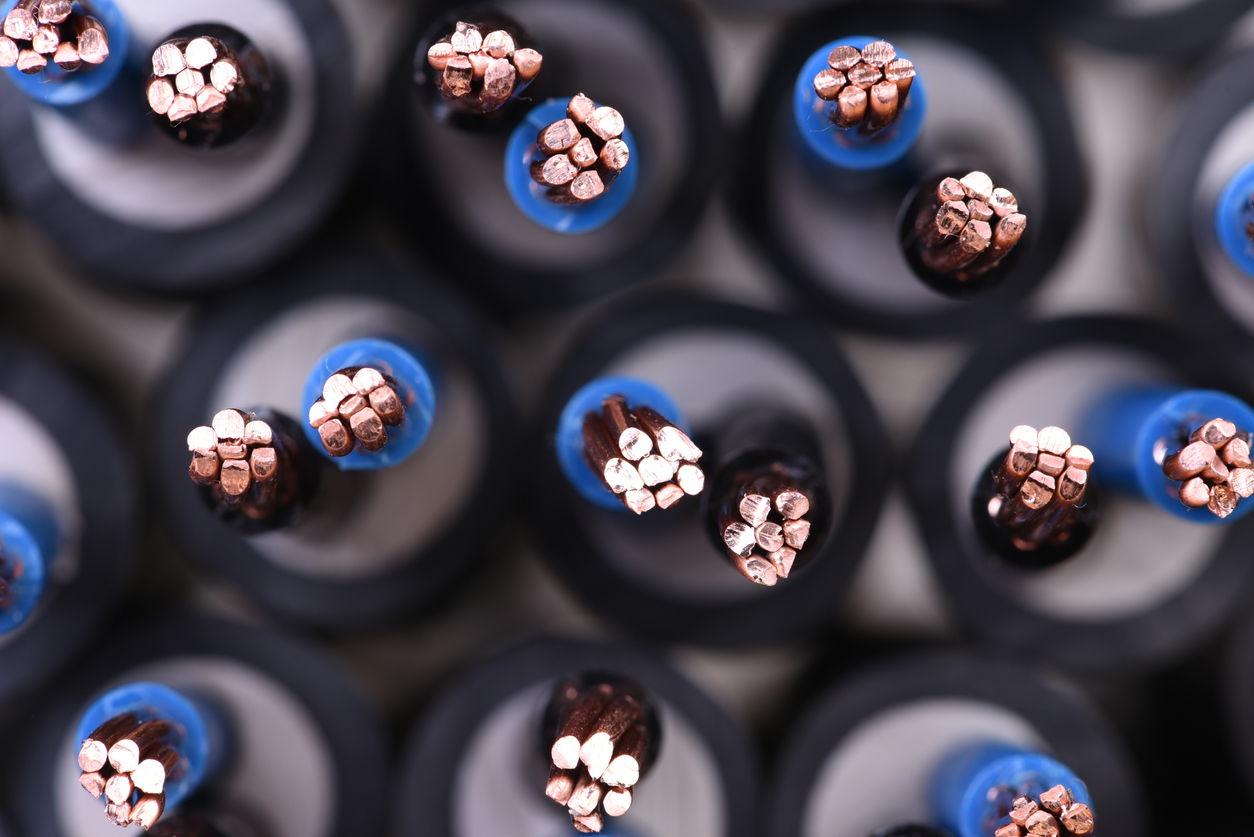
XACT manufactures custom cable assemblies and wire harnesses for power, signal, data, RF and mixed-function applications.
Open Architectures Depend on the Physical Layer
Open architecture initiatives are intended to make autonomous systems more interoperable, adaptable and easier to upgrade. Software frameworks can define how systems communicate, while payload interface standards can establish common mechanical, electrical and data requirements.
Those goals still depend on the physical interconnect system.
A payload cannot function as a plug-and-play module unless the platform provides compatible:
- Voltage and current capacity
- Grounding and bonding
- Data protocols
- Pin assignments
- Connector interfaces
- Shielding performance
- Environmental sealing
- Mechanical retention
- Cable routing and bend radius
- Identification and documentation
An Ethernet-based interface, for example, still requires the correct conductor geometry, impedance control, shielding and termination practices. An RF payload requires more than a connector that physically fits; the complete assembly must protect signal integrity across the required frequency range.
Open architectures therefore do not make cable design less important. They make consistent, well-documented interconnect design even more important.
Designing the Electrical Backbone for Future Payloads
No engineering team can predict every sensor or mission system that will be introduced over the life of a platform. Future-proofing does not mean designing for every possible configuration. It means avoiding unnecessary limitations that would make reasonable upgrades difficult.
Several design strategies can improve long-term flexibility.
Provide Practical Capacity for Growth
A cable trunk sized only for the original configuration may have no capacity for an added sensor, processing unit or communications system.
Where space and weight allow, engineers may consider:
- Spare conductors
- Additional shielded pairs
- Reserved connector positions
- Greater data capability than initially required
- Provisions for fiber-optic pathways
- Power distribution capacity for anticipated upgrades
These provisions should be intentional and documented. Adding unused conductors without a clear grounding, termination or identification strategy can create confusion rather than flexibility.
Standardize Interfaces Where It Adds Value
Standardized interfaces can simplify payload development, installation and maintenance. Common shell sizes, keying arrangements, voltage conventions and data interfaces can reduce the number of unique assemblies required across a fleet.
Standardization should not be applied blindly, however. A high-current propulsion connection, RF antenna assembly and low-voltage sensor interface have very different requirements.
The most effective strategy is often to standardize the platform side while allowing the replaceable payload harness to accommodate equipment-specific differences.
Use Replaceable Harness Segments
A single continuous cable may reduce the number of connectors, but it can also make service more difficult. If one termination is damaged, technicians may need to replace or rework a much larger assembly.
Dividing the system into accessible, replaceable segments can improve:
- Fault isolation
- Field repair
- Payload replacement
- Production repeatability
- Configuration control
- Long-term sustainment
The appropriate number of segments depends on electrical performance, environmental exposure, accessibility and reliability requirements.
Modular Does Not Mean Environmentally Simple
Connections that are easy to replace must still survive the maritime environment.
Depending on whether the assembly is installed inside a protected enclosure, exposed on deck or used in a submerged application, it may encounter:
- Salt spray and corrosion
- Moisture or water ingress
- Continuous vibration
- Wave impact and mechanical shock
- Abrasion
- UV exposure
- Temperature cycling
- Repeated flexing
- Hydrocarbon or chemical exposure
- Pressure changes
- Repeated connector mating
A modular interface that performs well during initial testing may become unreliable if its seals, strain relief or shielding degrade after repeated service.
Environmental performance therefore has to be considered across the entire assembly—not only at the connector face.
Cable jackets, backshells, boots, heat shrink, shielding, transitions and cable exits all contribute to long-term performance. Overmolded cable assemblies can provide integrated strain relief, sealed transitions and protection around vulnerable termination areas when the application supports a molded design.
For non-molded assemblies, properly selected backshells, boots, sleeving, heat shrink and protective braid can provide serviceable environmental and mechanical protection.
XACT also supports rugged and harsh-environment cable assemblies designed around application-specific exposure to moisture, vibration, abrasion, temperature and other operating conditions.
Maintainability Matters More on an Uncrewed Platform
A conventional vessel may have personnel onboard who can observe a developing problem, tighten a loose connection or investigate intermittent equipment behavior.
An autonomous platform may operate for extended periods without direct human access. A small interconnect failure can therefore interrupt a mission and require recovery of the vessel.
Modular cable architectures can improve maintainability by making assemblies easier to inspect, test and replace. Helpful features may include:
- Clear wire and cable identification
- Unique connector keying
- Accessible disconnect points
- Durable labels or marker sleeves
- Testable harness segments
- Documented pinouts
- Consistent assembly configurations
- Replaceable branches or transition assemblies
- Controlled service loops
- Protection against incorrect mating
These details may appear secondary during initial design, but they become increasingly important when multiple vehicles, payload configurations and replacement assemblies enter service.
Documentation and configuration control are equally important. A physically interchangeable cable is not necessarily electrically interchangeable. Drawings, revision history, bills of materials and test requirements should clearly identify which assemblies are approved for each platform and payload configuration.
Modular Cable Architecture Comparison
| Design Consideration | Fixed Wiring Architecture | Modular Cable Architecture |
|---|---|---|
| Payload integration | Frequently requires platform-level changes | Changes can be contained within payload-specific modules |
| Upgrade flexibility | Limited by original cable and connector design | Standardized pathways support planned evolution |
| Maintenance | Faults may require extensive troubleshooting or cable replacement | Replaceable segments improve fault isolation |
| Production | Numerous vehicle-specific cable runs | Repeatable trunks and interfaces can simplify production |
| Configuration control | Often tied to one equipment layout | Supports documented payload and harness variants |
| Future expansion | May require new cable routing | Can include reserved power, data or connector capacity |
| Field service | Longer repair and replacement procedures | Modules can be designed for faster replacement |
| Initial design effort | May appear simpler | Requires earlier architectural planning |
| Lifecycle value | Optimized for initial configuration | Designed to support multiple equipment generations |
A modular architecture is not automatically less expensive or less complex during initial development. It usually requires more deliberate planning at the beginning of the program.
The value emerges over time through more manageable upgrades, repeatable interfaces, easier service and reduced disruption to the core platform.
Treat Interconnects as a Strategic Subsystem
Cable assemblies are sometimes finalized after the hull, electronics and payload equipment have already been selected. At that stage, the cable design has to accommodate decisions made elsewhere in the system, even when the available routing space, connector access or shielding strategy is less than ideal.
A modular platform benefits from addressing interconnect requirements earlier.
Cable and harness considerations can influence:
- Equipment placement
- Bulkhead design
- Power distribution
- Grounding and bonding
- Payload bay dimensions
- Connector accessibility
- Service procedures
- Network architecture
- EMI control
- Weight distribution
- Qualification and testing
Early collaboration can also identify manufacturability concerns before the program reaches production.
XACT provides engineering design support for connector selection, cable construction, drawings, bills of materials, prototypes, new product introduction, engineering changes and design-for-manufacturability considerations.
The appropriate manufacturing approach may include molded or non-molded cable assemblies, internal or external wire harnesses, RF/coax assemblies, hybrid constructions or a combination of technologies.
How XACT Supports Modular Maritime Programs
XACT Engineered Manufacturing Solutions designs and manufactures custom cable assemblies, complex wire harnesses, overmolded interconnect systems, RF and coaxial assemblies, hybrid cable solutions and integrated electromechanical assemblies.
Support is available from initial development through production and long-term program sustainment, including:
- Connectorized cable assemblies
- Overmolded connectors and cable exits
- Molded strain relief and breakout transitions
- Internal and external wire harnesses
- Power and signal distribution harnesses
- Hybrid power, signal and data assemblies
- RF, coaxial and antenna-related assemblies
- Rugged shielding and cable protection
- Build-to-print manufacturing
- Build-from-sample support
- Prototype and new-product introduction
- Repair, refurbishment and recertification
- Documentation and engineering-change support
- Electrical, mechanical, environmental and RF testing
XACT operates manufacturing facilities in Houston, Texas, and Calgary, Alberta, supporting North American programs from prototype quantities through repeat production.
Build an Interconnect Architecture That Can Evolve With the Mission
Autonomous maritime platforms are being asked to remain operational longer, support more missions and integrate technology that may not exist when the original vessel is designed.
The cable architecture should not be the component that prevents that evolution.
By planning standardized interfaces, replaceable harness segments, scalable power and data pathways, environmental protection and clear configuration control early in development, engineering teams can create a platform that is easier to upgrade, manufacture and sustain.
XACT works with OEMs and engineering teams to develop custom cable assemblies, wire harnesses and rugged interconnect systems for demanding applications.
FAQ
What is a modular cable architecture?
A modular cable architecture divides a platform’s electrical interconnect system into standardized or replaceable sections. Common power and data backbones can connect to payload-specific harnesses, allowing equipment to be upgraded or replaced without rewiring the entire vessel.
Why are modular cable architectures important for USVs and UUVs?
USVs and UUVs may remain in service longer than the sensors, processors and communications systems installed during their original build. Modular cable architectures help platforms accommodate new equipment, mission requirements and interface technologies throughout their operational lives.
Can power, data and RF be combined in one cable assembly?
In some applications, yes. Hybrid cable assemblies can combine multiple functions within one construction. The design must address conductor sizing, heat, shielding, signal separation, impedance, connector compatibility and the environmental requirements of the application.
Are overmolded cable assemblies suitable for autonomous maritime systems?
Overmolding can provide strain relief, sealed cable exits and protection around connector terminations. Suitability depends on the required serviceability, connector type, environmental exposure and qualification requirements. Some interfaces are better served by non-molded backshells, boots or other removable protection.
Does XACT manufacture assemblies using military-specification connectors?
Yes. XACT manufactures custom cable assemblies and wire harnesses using customer-specified and application-selected connector systems, including military-specification connectors and high-reliability connector solutions.
Can XACT build from an existing drawing or sample?
Yes. XACT supports build-to-print and build-from-sample programs, including documentation development, repeat manufacturing, repair and replacement support. Engineering review may be used to confirm materials, dimensions, pinouts, shielding, environmental requirements and testing criteria.
What certifications and compliance programs support XACT’s defense work?
XACT’s quality and compliance credentials include AS9100:2016, ISO 9001:2015, IPC/WHMA-A-620, J-STD-001, ITAR registration, NIST/CMMC readiness, the Canadian Controlled Goods Program and the U.S./Canada Joint Certification Program.
XACT’s Houston facility holds CAGE Code 8HHW8, and its Calgary facility holds CAGE Code L1030.