Telescoping mobile systems need cable assemblies that move, extend, retract, and survive field deployment.

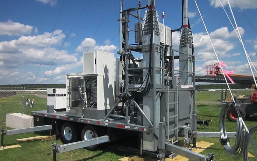
Mobile surveillance trailers, portable communication towers, emergency response units, deployable lighting masts, antenna systems, test platforms, and temporary field networks often require cable assemblies that travel with the equipment and continue working after repeated setup and teardown.

A straight cable may work in a static installation, but telescoping systems create different demands.

The cable assembly may need to support vertical movement, power, signal, data, radio frequency, outdoor exposure, repeated flexing, controlled routing, connector protection, and serviceability.

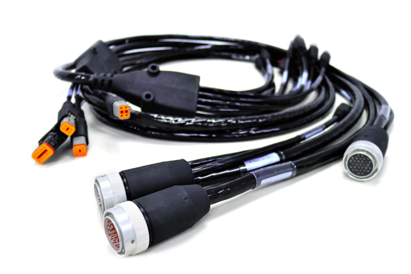
A black coiled cable with orange connectors, featuring multiple pins at each end, is shown on a white background.

Why Telescoping Mobile Systems Need Custom Cable Assemblies

Telescoping mobile systems are not fixed installations. They are transported, deployed, adjusted, retracted, stored, and redeployed. That means the cable assembly must support both electrical performance and mechanical movement.

Custom cable assemblies may be needed when the system includes:

  • Telescoping masts
  • Mobile surveillance trailers
  • Portable communication towers
  • Emergency response units
  • Deployable lighting
  • Antenna systems
  • Cameras or sensors
  • Radio frequency connections
  • Ethernet or data links
  • Power plus signal runs
  • Outdoor field deployment
  • Repeated extension and retraction
  • Rugged connector interfaces

The goal is to prevent the cable from becoming the part that limits deployment speed, reliability, or service life.

Coil Cord, Cable Reel, or Straight Cable?

The best cable format depends on how the system moves.

A straight cable may be acceptable when the equipment is fixed, protected, and does not require repeated extension or controlled storage.

A retractile coil cord may be useful when the system needs repeated extension and retraction in a compact space. Coil cords can help reduce loose cable, support vertical adjustment, and keep the assembly organized during movement.

A cable reel may be better when the cable needs to be transported, deployed over a distance, retrieved, and reused at a field site.

For mobile trailers, field communication systems, temporary networks, test equipment, and deployable power or data runs, cable reels can provide cleaner cable management and help protect the assembly during repeated use.

Design for Extension, Retraction, and Motion

Telescoping systems place mechanical stress on cable assemblies.

The cable may need to bend, twist, coil, retract, or move alongside a mast or vertical structure. If the design does not account for this motion, the assembly can fail at the conductor, jacket, connector, or transition point.

Important design inputs include:

  • Retracted length
  • Extended length
  • Extension ratio
  • Minimum bend radius
  • Coil diameter or routing path
  • Cable outer diameter
  • Flex life
  • Torsional movement
  • Rotational movement
  • Pull strength
  • Mounting method
  • Clamp points
  • Connector exit direction
  • Service access

The cable should be designed around how the equipment actually moves, not just the distance between two connection points.

Manage Power, Signal, Data, and RF in One System

Telescoping mobile systems often carry more than one electrical function.

A mast may support cameras, radios, antennas, lights, sensors, controls, or network equipment. That can require power, signal, data, Ethernet, control wiring, or radio frequency connections in the same moving system.

Hybrid cable assemblies can help reduce cable clutter by combining multiple functions into one engineered assembly when the application allows it.

Hybrid assemblies may help reduce:

  • Loose cable runs
  • Connector count
  • Routing complexity
  • Installation time
  • Support points
  • Field wiring variation
  • Setup errors
  • Service confusion

For telescoping systems, hybrid construction can be useful when power and data need to move together through a compact or exposed deployment path.

Four large black cable reels, part of a cable reel system, are placed on a wooden pallet in a warehouse, with boxes and more coiled cables visible in the background.

Support Ethernet and Data Transmission in Moving Assemblies

Mobile surveillance trailers, portable towers, and emergency response systems often rely on video, sensor, or network data.

That means the cable assembly may need to carry Ethernet, control signals, or other data lines while still surviving movement and outdoor exposure.

Data-focused design considerations include:

  • Cable geometry
  • Pair construction
  • Shielding
  • Connector termination
  • Bend radius
  • Repeated movement
  • Routing near power conductors
  • Electromagnetic interference exposure
  • Grounding strategy
  • Connector protection

Data performance should be considered alongside mechanical durability. A cable can look intact but still create data reliability problems if the construction, shielding, termination, or bend conditions are not appropriate.

Protect Against Outdoor Exposure

Telescoping mobile systems are often used outdoors.

Cable assemblies may be exposed to rain, ultraviolet exposure, dust, wind, oil, chemicals, abrasion, temperature swings, and repeated handling.

Environmental design inputs may include:

  • Water resistance
  • Ultraviolet stability
  • Oil resistance
  • Chemical compatibility
  • Abrasion resistance
  • Cold-weather flexibility
  • Heat exposure
  • Connector sealing
  • Jacket durability
  • Outdoor storage conditions
  • Cleaning exposure

The jacket, connector system, overmolding, sleeving, heat shrink, and cable protection strategy all affect long-term field reliability.

Use Overmolding to Protect Connector Transitions

Connector transitions are common failure points in telescoping mobile systems.

The cable-to-connector area may experience pulling, bending, vibration, outdoor exposure, impact, and repeated handling.

Overmolding can help improve:

  • Strain relief
  • Bend control
  • Sealing
  • Impact resistance
  • Handling durability
  • Repeatable cable exit geometry
  • Connector transition protection
  • Protection from moisture and debris

Overmolded cable assemblies may be useful for mast-mounted electronics, camera systems, antenna interfaces, lighting systems, portable communications equipment, and field-deployed control assemblies.

Choose Connectors for Field Deployment

Connectors in telescoping mobile systems must do more than mate correctly.

They may need to survive transportation, repeated deployment, vibration, moisture, dust, operator handling, and field maintenance.

Connector design questions include:

  • Is the connector exposed outdoors?
  • Does it need sealing?
  • Will it be mated and unmated frequently?
  • Does it need a locking mechanism?
  • Is it mounted to a panel, enclosure, mast, sensor, camera, or antenna?
  • Does it carry power, signal, data, Ethernet, or radio frequency?
  • Is shielding continuity required?
  • Does the connector need a backshell, boot, heat shrink, or overmold?
  • Is field replacement important?

Selecting the connector and cable together helps prevent problems at the interface.

Shielding Matters for Cameras, Radios, Antennas, and Data

Telescoping systems may carry signals in electrically noisy environments.

Mobile equipment may include generators, power supplies, radios, antennas, lighting circuits, controls, motors, batteries, and network devices.

Shielding may be important for:

  • Ethernet or data links
  • Camera systems
  • Sensor signals
  • Radio frequency or coaxial assemblies
  • Antenna connections
  • Control wiring
  • Telemetry systems
  • Long cable runs
  • Mixed power and signal routing

The shielding strategy should include cable construction, connector termination, grounding, routing, and metal braiding where appropriate.

Applications That Use Telescoping Mobile Cable Assemblies

Telescoping mobile cable assemblies may be used across many rugged and field-deployed systems.

Examples include:

  • Mobile surveillance trailers
  • Portable cell towers
  • Emergency response units
  • Temporary communications systems
  • Deployable antenna masts
  • Portable lighting towers
  • Field command systems
  • Test and measurement platforms
  • Industrial mobile trailers
  • Security systems
  • Utility field equipment
  • Remote monitoring systems
  • Military or tactical communication platforms

Each application has different electrical and environmental requirements, but the shared challenge is consistent: the cable assembly must move reliably without creating loose cable, connector strain, or deployment delays.

Mobile Surveillance Trailers

Mobile surveillance trailers may include cameras, antennas, lighting, batteries, solar charging, networking hardware, and control systems.

Cable assembly priorities may include:

  • Power and data integration
  • Camera and sensor connections
  • Mast routing
  • Outdoor connector sealing
  • Shielding for data reliability
  • Abrasion protection
  • Cable management during transport
  • Field serviceability
  • Overmolded connector transitions

Because these systems are repeatedly moved and redeployed, serviceable and protected cable assemblies can help reduce downtime and simplify maintenance.

Portable Communication Towers and Antenna Systems

Portable communication towers and antenna systems may require power, data, radio frequency, control, or grounding-related connections.

Cable assembly priorities may include:

  • Radio frequency or coaxial performance
  • Shielding
  • Connector sealing
  • Rugged cable exits
  • Mast movement
  • Controlled cable routing
  • Weather exposure
  • Setup and teardown speed
  • Field replacement

For communication systems, cable reliability can directly affect signal quality, uptime, and deployment readiness.

Emergency Response and Field Command Systems

Emergency response units and field command systems need equipment that works quickly after transport.

These systems may include radios, network equipment, cameras, power distribution, lighting, sensors, and deployable masts.

Cable assemblies should support:

  • Fast setup
  • Repeatable routing
  • Rugged handling
  • Clear labeling
  • Connector protection
  • Power plus signal integration
  • Data reliability
  • Outdoor use
  • Serviceability under time pressure

In these applications, the cable assembly should make deployment easier, not add another point of failure.

Repair and Recertification Can Extend Service Life

Telescoping mobile systems often use specialized assemblies that are handled repeatedly.

Over time, cable assemblies may be damaged by abrasion, connector strain, overextension, transport, weather, or repeated coiling and uncoiling.

Repair and recertification may be worth evaluating when assemblies are expensive, specialized, or difficult to replace quickly.

This may apply to:

  • Damaged field cables
  • Worn connector transitions
  • Jacket abrasion
  • Overmold damage
  • Failed terminations
  • Moisture ingress concerns
  • Field-return evaluation
  • Testing and documentation needs
  • Existing assemblies that need to return to service-ready condition

Validate the Assembly Before Production

A telescoping cable assembly should be tested in the real equipment whenever possible.

Prototype validation can check:

  • Retraction behavior
  • Extension length
  • Coil memory
  • Bend radius
  • Cable routing
  • Connector fit
  • Strain relief
  • Data performance
  • Shielding strategy
  • Outdoor protection
  • Mounting points
  • Installation sequence
  • Service access

A cable assembly can pass continuity testing and still fail if it does not move correctly with the mast or equipment.

When to Contact a Custom Cable Manufacturer

It may be time to contact a custom cable manufacturer when a telescoping mobile system includes:

  • Repeated extension and retraction
  • Field deployment
  • Outdoor exposure
  • Power plus data requirements
  • Ethernet or control signals
  • Radio frequency or antenna connections
  • Cameras or sensors
  • Rugged connector interfaces
  • Overmolded cable transitions
  • Shielding requirements
  • Cable reels or deployable cable management
  • Custom routing or length constraints
  • Repair or recertification needs
  • Prototype-to-production support

The earlier these requirements are defined, the easier it is to design an assembly that supports movement, reliability, serviceability, and field deployment.

Why Work With XACT

XACT supports custom cable assemblies, wire harnesses, overmolded cable systems, rugged interconnects, hybrid cable solutions, radio frequency cable assemblies, connector integration, repair and recertification, and cable protection systems for demanding applications.

For telescoping mobile systems, XACT is a strong fit when the assembly requires:

  • Rugged cable assemblies
  • Power and data integration
  • Radio frequency or coaxial assemblies
  • Ruggedized connector integration
  • Overmolded cable assemblies
  • Cable protection and strain relief
  • Shielding and metal braiding
  • Deployable cable reel systems
  • Field-serviceable interconnects
  • Repair, testing, and recertification support
  • Low- and medium-voltage interconnects

For mobile systems where deployment speed, cable movement, and field reliability matter, the cable assembly should be designed as an engineered part of the system.

See the Facilities Behind the Work

For mobile surveillance, communications, emergency response, defense, energy, industrial, and field-deployed equipment programs, supplier capability matters.

A dedicated manufacturing environment can support consistent cable assembly production, wire harness work, overmolded interconnects, repair and recertification, testing, fabrication, supply chain support, and value-added services.

For teams evaluating XACT’s North American manufacturing footprint, the Matrix XACT YouTube channel includes facility tour content for both Houston and Calgary.

FAQ

A telescoping mobile cable assembly is designed for equipment that extends, retracts, moves, or deploys in the field. These assemblies may support power, signal, data, radio frequency, cameras, antennas, lighting, or control systems.

A coil cord may be useful when the system needs repeated extension and retraction without loose cable getting in the way. It can help support vertical movement, compact storage, and controlled cable behavior.

A cable reel may be better when the cable needs to be transported, deployed over a distance, retrieved, stored, and reused. Cable reels are useful for field communications, temporary networks, test systems, and deployable power or data runs.

Applications include mobile surveillance trailers, portable communication towers, emergency response units, deployable antenna masts, portable lighting towers, field command systems, test platforms, utility trailers, and remote monitoring systems.

Yes. Hybrid cable assemblies can combine power, signal, data, control, or coaxial elements when the application requires cleaner routing, fewer cables, reduced connector count, or simplified installation.

Shielding may be needed when the assembly carries Ethernet, camera signals, sensor data, radio frequency, telemetry, or control signals near radios, antennas, generators, lighting circuits, or other noise sources.

Overmolding helps protect connector transitions by adding strain relief, bend control, sealing, impact resistance, and repeatable cable exit geometry. This is useful for assemblies exposed to movement, outdoor conditions, and repeated handling.

Some rugged or specialized telescoping cable assemblies may be candidates for repair, refurbishment, testing, or recertification, especially when replacement is costly or downtime needs to be reduced.

No. XACT focuses on custom cable assemblies, wire harnesses, overmolded cable systems, rugged interconnects, radio frequency cable assemblies, connector integration, hybrid cable solutions, and cable protection systems rather than fiber optic cable manufacturing.
Extreme temperatures can turn a standard cable assembly into a failure point.

Heat can soften, deform, crack, or accelerate aging in the wrong materials. Cold can make a cable stiff, brittle, difficult to route, or more likely to fail during movement. Add vibration, oil, moisture, chemicals, abrasion, and field handling, and material selection becomes one of the most important parts of custom cable assembly design.

For rugged equipment, oil and gas systems, mining hardware, transportation electronics, military systems, aerospace support equipment, industrial automation, outdoor sensors, and field-deployed devices, cable material selection should be tied to the real operating environment.

The right cable assembly is not just about conductor size or connector type. It is about how the full interconnect system performs under thermal, mechanical, electrical, and environmental stress.

Why Material Selection Matters in Custom Cable Assemblies

Cable assemblies are often specified around electrical requirements first.

That is important, but electrical performance is only part of the design.

A cable assembly also needs to survive:

  • High temperatures
  • Low temperatures
  • Thermal cycling
  • Flexing
  • Vibration
  • Shock
  • Abrasion
  • Moisture
  • Oils and fuels
  • Chemicals
  • Ultraviolet exposure
  • Connector strain
  • Field handling
  • Installation stress

The conductor, insulation, tubing, jacket, shielding, overmolding, connector interface, and cable protection materials all affect long-term reliability.

A cable that works during bench testing may fail in the field if the materials are not matched to the real environment.

Start With the Temperature Profile

Before choosing materials, define the actual temperature conditions.

Important questions include:

  • What is the normal operating temperature?
  • What is the maximum operating temperature?
  • What is the minimum operating temperature?
  • Will the cable be stored at temperatures more extreme than its operating range?
  • Will the cable move while cold?
  • Will the cable flex while hot?
  • Will the cable experience rapid temperature cycling?
  • Will the cable be near engines, motors, heaters, brakes, power electronics, or outdoor sun exposure?
  • Will the connector and cable transition see the same temperature as the cable body?

Temperature selection should consider the full assembly, not just the cable jacket. Conductors, insulation, shielding, fillers, adhesives, overmolding materials, heat shrink, boots, seals, and connectors all need to tolerate the application.

Conductor Selection for High-Temperature Applications

Conductors need to maintain electrical performance while surviving the mechanical and thermal demands of the application.

For higher-temperature environments, conductor decisions may include:

  • Conductor material
  • Plating
  • Strand count
  • Flexibility
  • Gauge size
  • Current carrying requirements
  • Termination method
  • Corrosion risk
  • Compatibility with insulation and connector materials

Higher strand counts may improve flexibility, which can matter when the assembly sees motion, vibration, or repeated handling.

In severe environments, conductor selection should also account for how the cable will be routed and terminated. A conductor that is technically suitable for the temperature may still fail early if it is forced into a tight bend, exposed to vibration, or poorly strain-relieved at the connector.

Conductor Selection for Cold Environments

Cold environments create different problems.

A cable assembly that feels flexible at room temperature may become stiff or difficult to handle in low temperatures. If the cable needs to move, coil, retract, deploy, or bend during cold operation, flexibility becomes a critical design input.

Cold-temperature conductor considerations include:

  • Strand count
  • Minimum bend radius
  • Flex life
  • Jacket flexibility
  • Insulation flexibility
  • Connector transition strain relief
  • Storage temperature
  • Handling during deployment
  • Repeated motion while cold

For field-deployed systems, cold storage can be just as important as cold operation. A cable assembly may sit in a vehicle, container, trailer, or outdoor enclosure before being deployed under load.

Insulation and Jacketing Are Not the Same Thing

Insulation and jacketing serve different purposes.

Insulation surrounds the conductor and supports electrical separation. The jacket protects the cable from the outside environment.

Both matter, but they solve different problems.

Insulation selection may be driven by:

  • Voltage
  • Temperature
  • Dielectric performance
  • Wall thickness
  • Flexibility
  • Chemical compatibility
  • Abrasion resistance
  • Termination requirements

Jacket selection may be driven by:

  • Oil resistance
  • Chemical exposure
  • Moisture
  • Ultraviolet exposure
  • Abrasion
  • Cut resistance
  • Flexibility
  • Cold bend performance
  • Outdoor use
  • Cleaning exposure
  • Mechanical protection

For rugged cable assemblies, jacket material often determines whether the cable survives real field use.

Tubing and Protective Layers Add Mechanical and Environmental Defense

Some cable assemblies need additional protection beyond insulation and jacketing.

Protective layers may include:

  • Tubing
  • Heat shrink
  • Braiding
  • Sleeving
  • Loom
  • Conduit
  • Grommets
  • Boots
  • Cable glands
  • Molded transitions
  • Potting
  • Overmolding

These layers can help protect against abrasion, strain, moisture, impact, and handling damage.

Tubing and cable protection should be selected around the failure risk. For example, a cable routed near sharp edges may need abrasion protection. A connector transition exposed to repeated handling may need overmolding. A cable bundle exposed to vibration may need strain relief and controlled routing.

High-Temperature Cable Assembly Design Considerations

High-temperature environments can occur near engines, motors, power electronics, brakes, heaters, industrial process equipment, outdoor enclosures, and machinery operating in hot climates.

Design considerations may include:

  • High-temperature insulation
  • Jacket material rating
  • Connector material rating
  • Overmold material compatibility
  • Heat shrink temperature rating
  • Adhesive compatibility
  • Shielding performance at temperature
  • Cable routing away from heat sources
  • Thermal cycling
  • Long-term material aging
  • Strain relief under heat exposure

High temperature can also affect flexibility, sealing, and mechanical strength. A material that survives a short-term temperature spike may not be appropriate for continuous exposure.

Low-Temperature Cable Assembly Design Considerations

Low-temperature applications may involve outdoor equipment, cold storage, mining, transportation, energy, defense, rail, aerospace ground support, or field-deployed systems.

Design considerations may include:

  • Cold bend performance
  • Flexibility at low temperature
  • Jacket brittleness
  • Connector seal performance
  • Overmold flexibility
  • Cable memory
  • Retraction behavior
  • Storage conditions
  • Deployment while cold
  • Impact resistance
  • Installation handling

Cold conditions can make cables harder to route and more vulnerable to cracking if the jacket, insulation, or protective layers are not selected correctly.

Thermal Cycling Can Be More Difficult Than Constant Temperature

Some applications do not operate at one stable temperature. They cycle between hot and cold conditions. This can happen in outdoor equipment, vehicles, aircraft support systems, field electronics, energy systems, and equipment that heats up during operation and cools down during storage.

Thermal cycling may affect:

  • Jacket expansion and contraction
  • Connector seals
  • Adhesion between cable and overmold
  • Potting compounds
  • Heat shrink
  • Insulation stability
  • Moisture ingress
  • Strain relief
  • Cable routing
  • Long-term fatigue

The full assembly should be evaluated for repeated temperature changes, not just maximum and minimum temperature ratings.

Liquid Exposure Can Drive Material Selection

Temperature is rarely the only environmental concern. Many rugged cable assemblies also need to resist liquids, including:

  • Oil
  • Fuel
  • Hydraulic fluid
  • Coolants
  • Cleaning agents
  • Salt water
  • Fresh water
  • Chemicals
  • Fertilizers
  • Industrial fluids

Liquid exposure can cause swelling, cracking, softening, loss of flexibility, seal failure, or jacket degradation.

When liquid exposure is possible, material compatibility should be considered across the entire assembly: jacket, insulation, overmold, heat shrink, seals, connector bodies, boots, and adhesives.

Flexibility and Flex Life Need to Be Defined Separately

A flexible cable is not automatically a high-flex cable. A cable may feel easy to bend during installation but still fail early under repeated motion. Another cable may feel more robust but be engineered for long flex life.

When specifying a cable assembly, define whether the cable will experience:

  • One-time installation bending
  • Occasional service movement
  • Continuous flexing
  • Torsion
  • Rolling motion
  • Retracting or coiling
  • Drag-chain movement
  • Vibration
  • Operator handling
  • Pulling or deployment

This distinction matters for robotics, automation, mobile equipment, deployable systems, coil cords, test equipment, and machine-mounted electronics.

Shielding and Temperature Must Work Together

Shielding may be needed when the assembly carries sensitive signals, data, control wiring, radio frequency, or coaxial connections.

In extreme environments, the shielding approach must also tolerate the mechanical and thermal demands of the system.

Shielding considerations include:

  • Foil shielding
  • Braid shielding
  • Metal braiding
  • Drain wires
  • Shield termination
  • Connector backshells
  • Grounding strategy
  • Flexibility
  • Temperature exposure
  • Abrasion risk
  • Chemical exposure
  • Routing near power conductors

Shielding should be designed as part of the full interconnect system. Cable construction, connector termination, grounding, and routing all affect performance.

Connector Choice Must Match the Cable Materials

A cable assembly is only as reliable as its weakest interface. Even if the cable materials are correct, the assembly may fail if the connector, backshell, seal, overmold, boot, or strain relief is not matched to the same environment.

Connector selection should consider:

  • Temperature range
  • Sealing
  • Vibration resistance
  • Mating cycles
  • Cable exit direction
  • Strain relief
  • Shielding continuity
  • Chemical exposure
  • Moisture exposure
  • Field serviceability
  • Locking method
  • Mounting style
  • Connector material compatibility

For rugged systems, connector selection should happen alongside cable material selection.

Overmolding Helps Protect the Cable-to-Connector Transition

The cable-to-connector transition is one of the most common failure points in rugged cable assemblies.

Overmolding can help protect that area by improving strain relief, bend control, sealing, impact resistance, and repeatable cable exit geometry.

Overmolding may be useful when the assembly is exposed to:

  • Repeated handling
  • Moisture
  • Dust
  • Oil
  • Chemicals
  • Vibration
  • Shock
  • Pulling
  • Outdoor exposure
  • Temperature cycling
  • Field deployment

Overmold material selection should be compatible with the cable jacket, connector, temperature range, and environmental exposure.

Hybrid Cable Assemblies Need Careful Material Planning

Hybrid cable assemblies can combine power, signal, data, control, or radio frequency elements into one engineered cable assembly.

They can simplify routing and reduce cable clutter, but the material selection becomes more complex.

Hybrid cable design may need to account for:

  • Different conductor gauges
  • Shielded and unshielded elements
  • Power and signal separation
  • Data performance
  • Bend radius
  • Jacket thickness
  • Outer diameter
  • Connector compatibility
  • Temperature exposure
  • Flex requirements
  • Termination method
  • Cable protection

Hybrid assemblies are useful when a system needs multiple electrical functions in one rugged, manageable interconnect.

Cable Reels and Deployable Systems Add Material Stress

Deployable cable assemblies experience handling that fixed cables do not. They may be transported, unwound, dragged, pulled, coiled, retrieved, and redeployed many times.

For cable reels and field-deployed systems, material selection should consider:

  • Jacket abrasion resistance
  • Cold flexibility
  • Bend radius
  • Coil memory
  • Connector protection
  • Shielding durability
  • Moisture exposure
  • Field handling
  • Cable weight
  • Repeated deployment
  • Storage conditions

XACT’s deployable cable reel systems can be supplied pre-loaded with custom cable assemblies, molded cable assemblies, shielding, rugged connector interfaces, and optional through-bulkhead quick-disconnect connectors.

Repair and Recertification Can Help Evaluate Material Failure

When a rugged cable assembly fails in the field, the failure mode can reveal whether the original material selection was appropriate.

Repair and recertification may help evaluate:

  • Jacket cracking
  • Abrasion damage
  • Connector failure
  • Overmold damage
  • Potting or sealing issues
  • Moisture ingress
  • Broken conductors
  • Shielding damage
  • Strain relief failure
  • Field-return condition

For expensive or specialized assemblies, repair and recertification can help determine whether the cable can be returned to service or whether a redesign is needed.

When to Contact a Custom Cable Manufacturer

It may be time to contact a custom cable manufacturer when the application includes:

  • Extreme heat
  • Extreme cold
  • Thermal cycling
  • Liquid exposure
  • Oil or chemical exposure
  • Outdoor deployment
  • High-flex movement
  • Vibration or shock
  • Rugged connectors
  • Overmolded transitions
  • Shielding requirements
  • Power plus signal integration
  • Custom routing or length constraints
  • Cable reels or deployable equipment
  • Repair or recertification needs
  • Prototype-to-production support

The earlier these details are defined, the easier it is to select materials that support performance, serviceability, and long-term reliability.

Why Work With XACT

XACT supports custom cable assemblies, wire harnesses, overmolded cable systems, rugged interconnects, hybrid cable solutions, radio frequency cable assemblies, connector integration, repair and recertification, and cable protection systems for demanding applications.

For extreme-temperature and harsh-environment applications, XACT is a strong fit when the assembly requires:

  • Rugged cable assemblies
  • Material selection support
  • Low- and medium-voltage interconnects
  • Power and signal integration
  • Ruggedized connector integration
  • Overmolded cable assemblies
  • Cable protection and strain relief
  • Shielding and metal braiding
  • Deployable cable systems
  • Field-serviceable assemblies
  • Repair, testing, and recertification support

For harsh environments, the cable assembly should be designed as an engineered part of the equipment, not treated as a commodity component.

See the Facilities Behind the Work

For industrial, energy, oil and gas, mining, transportation, defense, aerospace, and field-deployed equipment programs, supplier capability matters.

A dedicated manufacturing environment can support consistent cable assembly production, wire harness work, overmolded interconnects, repair and recertification, testing, fabrication, supply chain support, and value-added services.

For teams evaluating XACT’s North American manufacturing footprint, the Matrix XACT YouTube channel includes facility tour content for both Houston and Calgary.

FAQ

The best cable materials depend on the exact application, temperature range, motion, fluids, connectors, and exposure conditions. High-temperature and low-temperature environments may require different conductor, insulation, jacket, tubing, overmold, and connector materials.

Cable jackets can crack in cold environments when the material becomes too stiff or brittle for the bend radius, movement, or handling conditions. Cold bend performance should be considered when the cable will move, deploy, coil, or flex in low temperatures.

High heat can accelerate material aging, soften or deform jackets, affect insulation performance, weaken strain relief, damage seals, or reduce the life of overmolds and protective layers if the materials are not selected for the temperature range.

No. Flexibility describes how easily a cable bends. Flex life describes how well the cable survives repeated movement over time. A cable can feel flexible but still fail early in continuous flexing or vibration applications.

Overmolding should be considered when the connector transition needs strain relief, sealing, bend control, impact protection, or repeatable geometry. The overmold material should be compatible with the cable jacket, connector, temperature range, and environmental exposure.

The connector, seal, backshell, boot, and strain relief must survive the same environment as the cable. A cable built with the right materials can still fail if the connector interface is not suited to the temperature, fluids, vibration, or field handling.

Yes. Shielding can be used in harsh-temperature environments, but the shielding design, jacket, connector termination, grounding, and strain relief should all be selected around the application’s temperature, flex, abrasion, and electrical noise requirements.

Relevant fluids may include oil, fuel, hydraulic fluid, coolant, salt water, fresh water, chemicals, cleaning agents, fertilizers, and industrial process fluids. Compatibility should be evaluated across the cable jacket, insulation, overmold, seals, connectors, and protective layers.

A cable reel should be considered when the assembly needs to be transported, deployed, retrieved, and reused. Material selection should account for abrasion, cold flexibility, bend radius, connector protection, shielding durability, and field handling.

Some rugged cable assemblies may be candidates for repair, refurbishment, testing, or recertification. This can help evaluate material failure, reduce downtime, and extend the life of expensive or specialized assemblies.

No. XACT focuses on custom cable assemblies, wire harnesses, overmolded cable systems, rugged interconnects, radio frequency cable assemblies, connector integration, hybrid cable solutions, and cable protection systems rather than fiber optic cable manufacturing.
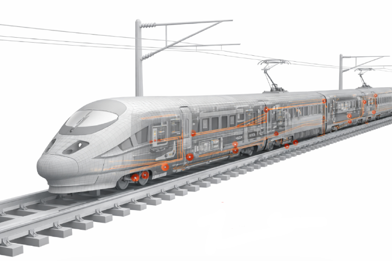
Smaller electronics often create bigger cable assembly challenges.

As devices become more compact, engineers still need to route power, signal, data, shielding, connectors, and strain relief through limited space. The cable assembly may need to be smaller, lighter, more flexible, and easier to integrate without compromising reliability.

That is where miniaturized cable design matters.

For aerospace equipment, medical devices, industrial automation, robotics, defense electronics, sensors, portable systems, and compact field-deployed hardware, the goal is not simply to make the cable smaller. The goal is to reduce size while preserving electrical performance, mechanical durability, connector reliability, and serviceability.

What Miniaturized Cable Design Means

Miniaturizing a cable assembly means reducing the size, weight, or routing footprint of the interconnect system while still meeting the application’s requirements.

That may involve:

  • Smaller cable outer diameter
  • Reduced insulation wall thickness
  • Compact conductor selection
  • Miniature connectors
  • Hybrid cable construction
  • Higher-density pin layouts
  • Smaller bend radius
  • Tighter routing paths
  • Integrated shielding
  • Overmolded strain relief
  • Compact breakout design
  • Reduced part count

The best miniaturized cable design starts with the full system, not just the cable. The connector, cable, shielding, jacket, overmold, routing path, bend radius, and termination method all need to work together.

Miniature connectors

Why Compact Cable Assemblies Are Difficult to Design

Smaller does not automatically mean simpler.

When a cable assembly gets smaller, the design often becomes more sensitive to material choice, conductor size, connector selection, shielding, termination quality, and strain relief.

Common challenges include:

  • Limited routing space
  • Smaller connector interfaces
  • Higher conductor density
  • Tighter bend radius
  • Reduced jacket thickness
  • Less room for shielding
  • More difficult termination
  • Increased strain at connectors
  • Heat buildup in compact spaces
  • Serviceability limitations
  • Higher risk of damage during assembly or installation

A miniaturized cable assembly must be designed carefully so that the size reduction does not create new failure points.

Start With the End Application

Miniaturization should be driven by the application, not by size alone.

Before reducing cable size, define what the assembly must do and where it will be used.

Important design inputs include:

  • Available routing space
  • Electrical load
  • Signal type
  • Data requirements
  • Shielding requirements
  • Connector type
  • Bend radius
  • Flex requirements
  • Temperature exposure
  • Moisture or fluid exposure
  • Vibration or shock
  • Serviceability
  • Installation method
  • Testing requirements
  • Production volume

A compact assembly used inside a protected enclosure has different requirements than a miniaturized harness used in a rugged field device, aerospace system, robot arm, or machine-mounted sensor.

Use Miniature Connectors to Reduce Interface Size

Connectors are often one of the largest parts of a cable assembly.

Miniature connectors can help reduce the size and weight of the interconnect system while supporting power, signal, data, or high-density connections.

Miniature connector options may be useful when the application involves:

  • Space-constrained electronics
  • Compact sensors
  • High-density interconnects
  • Portable devices
  • Rugged small-form-factor systems
  • Aerospace equipment
  • Medical devices
  • Industrial automation
  • Military electronics
  • Power, signal, or data transmission
  • Sealed or environmentally protected interfaces

Connector selection should still account for durability, mating cycles, sealing, shielding continuity, strain relief, cable exit direction, and field serviceability.

Reduce Cable Diameter Carefully

Reducing cable diameter can help save space, reduce weight, and simplify routing.

But reducing diameter can also affect:

  • Current capacity
  • Voltage drop
  • Flex life
  • Shielding effectiveness
  • Jacket durability
  • Termination strength
  • Pull strength
  • Bend radius
  • Heat dissipation
  • Manufacturing repeatability

The cable should be sized around performance requirements, not just physical space. A cable that fits the enclosure but cannot handle the current, movement, temperature, or installation stress is not a successful design.

Conductor Selection Affects Size and Performance

Conductor selection is central to miniaturized cable design.

Smaller conductors can reduce cable diameter, but they may also change current capacity, voltage drop, flexibility, and termination requirements.

Design considerations include:

  • Wire gauge
  • Conductor material
  • Strand count
  • Plating
  • Flexibility
  • Current requirements
  • Signal integrity
  • Termination method
  • Space available inside the connector
  • Mechanical stress at the termination

Higher strand counts may improve flexibility, while conductor material and gauge choices can affect ampacity and routing. The right conductor selection depends on the electrical and mechanical requirements of the system.

Reducing Wall Thickness Can Save Space

Insulation and jacket wall thickness can affect overall cable size.

In some applications, thinner insulation or jacket materials can reduce diameter while maintaining required electrical and mechanical performance. But this depends on the material, voltage, temperature, abrasion risk, chemical exposure, and handling conditions.

Reducing wall thickness should be evaluated carefully because it may affect:

  • Dielectric strength
  • Abrasion resistance
  • Cut resistance
  • Flex life
  • Moisture protection
  • Termination processing
  • Long-term durability
  • Mechanical protection

Thin-wall construction can be useful, but only when the material and application support it.

Hybrid Cable Assemblies Can Reduce Cable Count

Miniaturization does not always mean shrinking a single cable.

Sometimes the better approach is to combine multiple cables into one hybrid assembly.

A hybrid cable assembly can integrate power, signal, data, control, or radio frequency elements into one engineered solution when the application allows it.

Hybrid assemblies can help reduce:

  • Total cable count
  • Connector count
  • Routing complexity
  • Bundle size
  • Installation time
  • Service confusion
  • Harness clutter
  • Weight
  • Space consumed by separate cable runs

This approach can be useful in compact devices, field electronics, robotics, industrial automation, sensors, medical equipment, and military systems where multiple functions need to pass through one limited routing path.

Shielding Becomes More Important in Dense Designs

As cable assemblies become smaller and more densely packed, shielding and signal integrity become more important.

Compact systems may place power conductors, signal wires, data lines, motors, radios, antennas, and electronics close together. This can increase the risk of electromagnetic interference, radio frequency interference, crosstalk, or signal degradation.

Shielding considerations include:

  • Foil shielding
  • Braid shielding
  • Metal braiding
  • Drain wires
  • Shield termination
  • Connector backshells
  • Grounding strategy
  • Separation of power and signal
  • Cable geometry
  • Routing near noise sources

The shielding design should be planned with the connector and termination method. A shielded cable with poor shield termination may not deliver the intended protection.

Miniaturized Cable Assemblies Still Need Strain Relief

Compact cable assemblies are often vulnerable at the connector transition.

When cables get smaller, there may be less material to absorb bending, pulling, vibration, and handling stress. This makes strain relief especially important.

Strain relief options may include:

  • Overmolding
  • Boots
  • Heat shrink
  • Potting
  • Cable clamps
  • Grommets
  • Molded breakouts
  • Bend relief features
  • Controlled cable exit angles

The goal is to protect the transition between the cable and connector without adding unnecessary size or stiffness.

Overmolding Can Protect Small Connector Interfaces

Overmolding can be especially useful in compact cable assemblies where the connector transition needs protection but space is limited.

Overmolding can help improve:

  • Strain relief
  • Bend control
  • Sealing
  • Impact resistance
  • Handling durability
  • Repeatable cable exit geometry
  • Connector protection
  • Moisture and debris resistance

For miniature cable assemblies, overmolding should be designed around connector size, cable diameter, jacket compatibility, material flexibility, bend radius, and installation space.

Design for Flexibility and End-User Handling

Smaller cables may be easier to route, but they are not automatically more durable.

Miniaturized cable assemblies may need to remain flexible for installation, service, or end-user comfort. This is especially important in handheld equipment, wearable systems, medical devices, portable tools, robotics, and field electronics.

Design inputs may include:

  • How often the cable moves
  • Whether the cable flexes during operation
  • Whether the cable is handled by users
  • Bend radius requirements
  • Torsion or rotational movement
  • Strain near the connector
  • Cable stiffness
  • Jacket feel
  • Routing constraints

A compact assembly should not create a poor user experience or introduce premature fatigue failures.

Rugged Small-Form-Factor Systems Need Environmental Protection

Miniaturization is often associated with indoor electronics, but many compact systems are used in harsh environments.

Rugged small-form-factor cable assemblies may need protection from:

  • Moisture
  • Dust
  • Oil
  • Chemicals
  • Temperature swings
  • Ultraviolet exposure
  • Vibration
  • Shock
  • Abrasion
  • Repeated handling
  • Field service

In these cases, the challenge is balancing compact size with sealing, cable protection, connector durability, and strain relief.

Connector and Assembly Design Should Be Planned Together

The connector and cable should not be selected separately.

A compact connector may look attractive, but it must be compatible with the cable construction, conductor count, shield termination, overmolding approach, bend radius, and assembly process.

Connector and assembly planning should include:

  • Pin count
  • Contact density
  • Cable outer diameter
  • Wire gauge compatibility
  • Shield termination method
  • Cable exit direction
  • Mating cycles
  • Sealing requirements
  • Strain relief
  • Overmold compatibility
  • Tooling requirements
  • Testing requirements

This is where early engineering support can help avoid designs that are compact on paper but difficult to build or unreliable in use.

Miniaturization Can Improve Routing and Serviceability

Compact cable assemblies can reduce clutter, but only when the design is organized.

A smaller cable assembly may help with routing, airflow, fixture spacing, enclosure access, and installation speed. But if the assembly becomes difficult to identify, disconnect, or replace, it can create new service problems.

Serviceability considerations include:

  • Clear labeling
  • Connector orientation
  • Keyed connectors
  • Defined routing paths
  • Replaceable assemblies
  • Modular breakouts
  • Bend radius control
  • Access to mating points
  • Reduced adapter use
  • Consistent assembly geometry

A miniaturized assembly should save space without making maintenance harder.

Applications for Miniaturized Cable Assemblies

Miniaturized cable assemblies may be useful across many compact and high-performance systems.

Examples include:

  • Aerospace electronics
  • Defense electronics
  • Medical devices
  • Industrial automation
  • Robotics
  • Compact sensors
  • Test equipment
  • Portable electronics
  • Rugged handheld devices
  • Small unmanned systems
  • Machine vision modules
  • Field-deployed monitoring devices
  • High-density control systems

The strongest fit for XACT is where compact design intersects with ruggedness, connectorization, shielding, overmolding, power and signal integration, or field-serviceable hardware.

Repair and Recertification Can Help Evaluate Compact Assembly Failures

Small cable assemblies can be difficult to inspect and repair, especially when connectors, shields, overmolds, or breakouts are tightly integrated.

When compact assemblies fail, repair and recertification can help evaluate:

  • Connector damage
  • Broken conductors
  • Shielding damage
  • Overmold failure
  • Potting or sealing issues
  • Strain relief failure
  • Moisture ingress
  • Termination problems
  • Field-return condition

For specialized or expensive assemblies, evaluation can help determine whether repair is practical or whether a design change is needed.

When to Contact a Custom Cable Manufacturer

It may be time to contact a custom cable manufacturer when a compact system requires:

  • Smaller cable diameter
  • Miniature connectors
  • High-density interconnects
  • Power plus signal integration
  • Data or high-speed transmission
  • Shielding
  • Overmolded strain relief
  • Rugged environmental protection
  • Tight bend radius
  • Custom breakouts
  • Reduced cable count
  • Low- or medium-voltage interconnects
  • Prototype-to-production support

The earlier these requirements are discussed, the easier it is to reduce size without compromising performance or reliability.

Why Work With XACT

XACT supports custom cable assemblies, wire harnesses, overmolded cable systems, rugged interconnects, miniature connector integration, hybrid cable solutions, radio frequency cable assemblies, repair and recertification, and cable protection systems for demanding applications.

For miniaturized cable design, XACT is a strong fit when the assembly requires:

  • Compact cable assemblies
  • Miniature connectors
  • High-density interconnects
  • Power, signal, and data integration
  • Shielding and metal braiding
  • Ruggedized connector integration
  • Overmolded strain relief
  • Custom breakouts
  • Low- and medium-voltage interconnects
  • Prototype-to-production support
  • Field-serviceable compact assemblies

For small-form-factor systems, the cable assembly should be designed as part of the product, not treated as an afterthought.

See the Facilities Behind the Work

For aerospace, defense, medical, industrial automation, robotics, field electronics, and compact equipment programs, supplier capability matters.

A dedicated manufacturing environment can support consistent cable assembly production, wire harness work, overmolded interconnects, testing, fabrication, repair and recertification, supply chain support, and value-added services.

For teams evaluating XACT’s North American manufacturing footprint, the Matrix XACT YouTube channel includes facility tour content for both Houston and Calgary.

FAQ

Miniaturized cable design reduces the size, weight, or routing footprint of a cable assembly while preserving required power, signal, data, shielding, connector, and mechanical performance.

Miniature connectors should be considered when the application has limited space, high-density interconnect needs, compact electronics, rugged small-form-factor hardware, or power, signal, and data requirements in a smaller interface.

Yes, but it must be designed carefully. Rugged compact cable assemblies may require appropriate jacket materials, shielding, strain relief, overmolding, sealed connectors, and protection from vibration, moisture, abrasion, and handling.

Cable diameter may be reduced through conductor selection, thinner insulation or jacketing, hybrid cable construction, compact connector selection, optimized shielding, and careful routing design.

A cable that is too small may have inadequate current capacity, poor flex life, weak strain relief, limited shielding, difficult termination, excessive voltage drop, or reduced mechanical durability.

Hybrid cable assemblies can combine power, signal, data, control, or radio frequency elements into one compact assembly when the application supports it.

Shielding matters because compact systems often place conductors, electronics, motors, radios, antennas, and data lines close together. Shielding can help reduce electromagnetic interference, radio frequency interference, and crosstalk.

Yes. Overmolding can protect small connector transitions by adding strain relief, bend control, sealing, impact resistance, and repeatable cable exit geometry.

Miniaturized cable assemblies are used in aerospace electronics, defense electronics, medical devices, robotics, industrial automation, compact sensors, test equipment, rugged handheld devices, field electronics, and high-density control systems.

Some compact cable assemblies may be candidates for evaluation, repair, testing, or recertification, depending on the failure mode, connector type, overmold condition, shielding damage, and service requirements.

No. XACT focuses on custom cable assemblies, wire harnesses, overmolded cable systems, rugged interconnects, radio frequency cable assemblies, connector integration, hybrid cable solutions, and cable protection systems rather than fiber optic cable manufacturing.
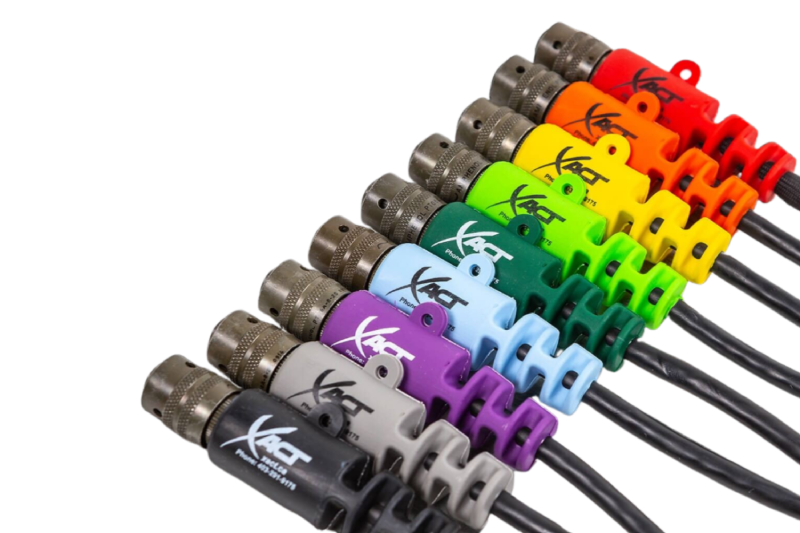
Rail modernization projects rarely start from a clean slate.

Most fleets are decades old, built on legacy systems that weren’t designed for today’s technology. But replacing entire electrical systems isn’t practical—it’s expensive, slow, and disruptive to operations.

That’s why rail retrofit wiring comes down to one objective:

Replace what’s failing—without breaking everything else.

Why Legacy Harness Replacement Becomes a Bottleneck

Rail systems rely on complex wiring harnesses that connect:

  • Door control systems
  • Lighting systems
  • Control panels and modules
  • Communication and signaling systems

Over time, these harnesses degrade due to:

  • Vibration and mechanical stress
  • Moisture and environmental exposure
  • Material aging
  • Obsolete connectors and components

When they fail, the issue isn’t just replacement—it’s compatibility.

The Real Risk: Turning a Retrofit Into a Redesign

Most retrofit programs don’t fail at the system level—they fail at the interconnect level.

If a replacement harness doesn’t match the original system, it creates:

  • Connector mismatches
  • Routing and fitment issues
  • Electrical inconsistencies
  • Installation delays

What should be a straightforward swap turns into engineering rework, redesign, and extended downtime.

The Right Approach: Form-Fit-Function Replacement

The most effective way to handle rail retrofit wiring is:

Match the original harness exactly—then improve performance where it matters.

Form-fit-function replacement ensures:

  • Same geometry and physical layout (form)
  • Same mounting and routing compatibility (fit)
  • Same electrical behavior (function)

With upgrades in:

  • Materials
  • Sealing
  • Durability
  • Labeling and install clarity

This keeps the system stable while improving reliability.

Where Retrofit Harnesses Are Used Most

Rail MRO and modernization programs consistently target the same systems:

Door Control Systems

  • High cycle wear components
  • Frequent failure points
  • Retrofit kits reduce install time

Lighting and Interior Systems

  • Transition to newer technologies
  • Requires compatibility with legacy wiring

Control Panels and Modules

  • Integration of updated electronics
  • Requires stable interconnects

Legacy Panel Rewiring

  • Replacement of obsolete components
  • Requires exact interface matching

These are repeatable applications across entire fleets.

What Makes a Retrofit Cable Assembly Work

Successful retrofit assemblies are built for installation—not just function.

Exact Interface Matching

  • Connector compatibility
  • Pinout accuracy
  • Mechanical fit

Pre-Labeled and Kitted Designs

  • Faster installs
  • Reduced technician error
  • Consistent deployment across assets

Environmental Protection

  • Sealed connections
  • Vibration resistance
  • Durable jacketing

Rapid Turnaround

  • Aligns with maintenance schedules
  • Reduces downtime

The Business Case: When Retrofit Makes Sense vs When Redesign Is the Better Move

Not every rail upgrade should follow the same path.

Retrofit (Form-Fit-Function Replacement)

Best when:

  • The system architecture still works
  • Specific components are failing or obsolete
  • Downtime must be minimized
  • Fleet-wide repeatability is required

Advantages:

  • Lower engineering cost
  • Faster deployment
  • Minimal disruption

Redesign (System-Level Upgrade)

Best when:

  • The system can’t support new technology
  • Performance requirements have changed significantly
  • Safety or compliance standards have evolved
  • Multiple subsystems need to be upgraded together

Advantages:

  • Enables full system optimization
  • Supports new functionality
  • Removes legacy limitations

The Practical Reality

Most rail programs combine both:

  • Retrofit harness replacements to maintain compatibility
  • Targeted redesigns where systems need to evolve

The goal isn’t to avoid redesign—it’s to avoid unnecessary redesign.

Why Rail MRO Demands Speed and Repeatability

Maintenance environments don’t allow for trial and error.

They require:

  • Fast installation
  • Clear documentation
  • Minimal on-site engineering

That’s why depot-installable cable assemblies and pre-labeled retrofit kits are critical.

When done right, they:

  • Reduce install time
  • Eliminate guesswork
  • Enable consistent upgrades across fleets

Where Retrofit Programs Break Down

Common failure points include:

  • Incomplete legacy documentation
  • Poor replication of original harness geometry
  • Lack of labeling or install guidance
  • Long lead times
  • Underestimating environmental conditions

These problems show up during installation—not during planning.

What This Means for Rail Operators and MRO Providers

If you’re managing:

  • Fleet modernization programs
  • Maintenance operations
  • System upgrades

Then interconnect strategy directly impacts:

  • Downtime
  • Labor efficiency
  • Total program cost

Getting the harness right simplifies everything else.

Quick Retrofit Checklist

  • Match legacy form-fit-function exactly
  • Validate connector and pinout compatibility
  • Use ruggedized materials
  • Pre-label and kit assemblies
  • Plan for repeatability across fleet upgrades

Need Help With a Retrofit Program?

Rail retrofit wiring projects don’t fail because of major systems—they fail at the interconnect level.

FAQ

Rail retrofit wiring involves replacing or upgrading cable assemblies and wiring harnesses in existing rail systems without redesigning the entire electrical architecture.

It is a replacement that matches the original component’s physical design, mounting, and electrical performance so it can be installed without modifying surrounding systems.

They are replaced due to wear, environmental exposure, obsolescence, or system upgrades that require improved reliability or compatibility.

Retrofit cable kits are pre-labeled, pre-configured cable assemblies designed for fast installation during maintenance or modernization work.

By using replacement harnesses that match the original system’s form, fit, and function, allowing upgrades without impacting surrounding components.

Labeling reduces installation errors, speeds up maintenance, and ensures consistent implementation across multiple assets or fleet upgrades.

If you’re comparing overmolding, potting, and heat shrink, you’re not just choosing a process—you’re deciding how your cable assembly will hold up under real conditions.

Each method solves a different problem. The mistake is assuming they’re interchangeable.

Overmolding: When You Need Strength + Sealing

Overmolding creates a sealed, bonded transition between cable and connector. It’s the go-to for assemblies that can’t fail in the field.

Best fit:

  • Outdoor or harsh environments
  • High vibration or repeated movement
  • Applications requiring sealing (IP-rated)

What you get:

  • Built-in strain relief
  • Strong environmental sealing
  • Long-term durability

Tradeoff:

  • Higher upfront tooling cost
  • Not reworkable
Overmolding vs Potting

Potting: When Internal Protection Matters

Potting fills internal cavities with resin to protect terminations, electronics, or sensitive components.

Best fit:

  • Internal component protection
  • Vibration or shock exposure
  • High-voltage insulation support

What you get:

  • Encapsulation of internal components
  • Moisture and chemical resistance
  • Added electrical insulation

Tradeoff:

  • Doesn’t provide strong external strain relief
  • Adds weight
  • Hard to inspect or rework

Heat Shrink: When You Need a Simple, Flexible Option

Heat shrink is widely used because it’s fast and cost-effective—but it’s not designed for demanding environments.

Best fit:

  • Basic insulation or bundling
  • Controlled environments
  • Prototyping or low-cost builds

What you get:

  • Quick installation
  • Low cost
  • Flexible application

Tradeoff:

  • Minimal strain relief
  • Limited environmental sealing
  • Shorter lifespan under stress
Overmolding vs Potting

What Actually Drives the Decision

Forget the terminology—focus on what matters in your application:

  • Strain relief needed? → Overmolding
  • Internal protection needed? → Potting
  • Cost-sensitive and low stress? → Heat shrink

Why These Methods Get Misapplied

Most failures come from one issue:

Choosing based on cost instead of risk.

  • Heat shrink used where mechanical stress exists
  • Potting expected to handle external strain
  • Overmolding skipped to reduce upfront cost

That decision usually shows up later as:

  • Field failures
  • Maintenance costs
  • Downtime

When One Method Isn’t Enough

In demanding applications, combining methods is common:

  • Overmolding + potting → full protection (external + internal)
  • Heat shrink + overmolding → added insulation + strain relief

Quick Decision Guide

  • Movement + environment → Overmolding
  • Internal electronics → Potting
  • Light-duty / cost-driven → Heat shrink
  • Critical system → Combine methods

Need Help Choosing?

If you’re evaluating these options, you’re already past generic solutions.

FAQ

Overmolding protects the external cable-to-connector transition, providing strain relief and sealing. Potting protects internal components, such as terminations or electronics, by encapsulating them in resin.

Heat shrink is suitable for basic insulation and bundling, but it does not provide strong strain relief or long-term protection in harsh environments.

Use overmolded assemblies when you need:

  • Environmental sealing
  • Mechanical strength
  • Long-term durability in harsh conditions

Yes. Many high-reliability assemblies use both:

  • Potting for internal protection
  • Overmolding for external durability and strain relief

Overmolding is typically the most durable option for external protection, especially in environments with vibration, moisture, or mechanical stress.

Designing cable assemblies for high-speed data and RF applications is not about getting power from point A to point B.

It’s about protecting signal integrity across the entire system.

At higher speeds and frequencies, cables behave like controlled transmission paths. That means impedance, shielding, materials, and connector transitions all directly impact performance. Small mistakes don’t stay small—they show up as signal loss, noise, or outright failure.

Why High-Speed and RF Design Changes Everything

Once you move into high-speed data or RF, three things happen:

  • Signals become sensitive to impedance changes
  • Loss increases with frequency
  • Interference becomes a real threat

That’s why high speed data cable assembly design and RF cable assembly design require tighter control over every variable—not just the cable itself, but how it’s terminated, routed, and integrated.

Impedance Control: Where Everything Starts

If impedance isn’t controlled, nothing else matters.

High-speed and RF systems rely on consistent impedance across:

  • The cable
  • The connector
  • The transition between them

When impedance is stable:

  • Signals pass cleanly
  • Reflections are minimized
  • Data integrity holds

When it’s not:

  • Signals reflect back
  • Energy is lost
  • Errors increase

Typical systems are designed around standard impedances like 50 ohms or 75 ohms. Deviations—even small ones—create measurable performance issues.

RF Performance Comes Down to Frequency and Loss

RF design starts with understanding the frequency range of the application.

As frequency increases:

  • Signal attenuation increases
  • Cable selection becomes more critical
  • Connector precision matters more

Higher frequency systems demand:

  • Tighter impedance control
  • Better shielding
  • Lower-loss materials

This is where standard cable approaches break down. RF assemblies require precision design and manufacturing, not just assembly.

VSWR: The Signal Integrity Check You Can’t Ignore

VSWR (Voltage Standing Wave Ratio) measures how much signal is being reflected back due to impedance mismatch.

  • Ideal: 1:1 (no reflection)
  • Higher values = more signal loss

High VSWR leads to:

  • Reduced power transfer
  • Increased heat
  • System instability

Minimizing VSWR requires:

  • Matching impedance across all components
  • Maintaining consistent geometry
  • Eliminating abrupt transitions

If your VSWR is off, the system performance will be too.

Shielding and EMI: Where Designs Break Down

At high speeds and frequencies, noise is no longer a background issue—it’s a primary failure driver.

Without proper shielding:

  • Signals degrade
  • Crosstalk increases
  • Data errors occur

Effective shielding strategies include:

  • Foil + braid combinations
  • Proper grounding
  • Controlled cable routing

This becomes critical in environments with:

  • High electrical noise
  • Dense electronics
  • Mixed signal types

Connectors: The Most Overlooked Failure Point

Most signal integrity issues don’t come from the cable—they come from the transition points.

Connectors must:

  • Match system impedance
  • Maintain consistent geometry
  • Support required frequency range

Poor connector selection leads to:

  • Impedance discontinuities
  • Reflection
  • Increased VSWR

In high-speed and RF systems, connectors are not accessories—they are part of the electrical path.

Materials and Construction Drive Performance

Material selection directly impacts performance at high frequencies.

Key factors include:

  • Dielectric material → controls signal propagation and impedance
  • Conductor quality → affects signal loss
  • Shielding design → reduces interference
  • Cable geometry → maintains consistency

Even minor inconsistencies in construction can lead to measurable signal degradation.

Testing: Where Theory Meets Reality

High-speed and RF assemblies must be validated, not assumed.

Common testing approaches:

  • Impedance verification
  • Reflection and loss measurement
  • Signal integrity validation

Without testing, there’s no way to confirm real-world performance.

Where Designs Typically Fail

Most issues trace back to the same problems:

  • Impedance mismatches between components
  • Inadequate shielding
  • Incorrect connector selection
  • Poor transitions between cable and connector
  • Lack of validation testing

At high speed and RF, there’s no margin for error.

What This Means for Your System

If your application involves:

  • High-speed data transmission
  • RF signals
  • Long cable runs
  • EMI-sensitive environments

Then cable design is not a commodity decision—it’s a system-level engineering requirement.

Quick Design Checklist

  • Maintain consistent impedance across the entire system
  • Select cable based on frequency requirements
  • Minimize VSWR through proper design
  • Use effective shielding strategies
  • Validate performance through testing

Need Help Getting It Right?

High-speed and RF systems don’t tolerate shortcuts.

FAQ

A high-speed data cable assembly is designed to transmit data at high frequencies while maintaining signal integrity through controlled impedance, shielding, and precise construction.

An impedance-controlled cable is manufactured to maintain a consistent electrical impedance along its length, reducing signal reflection and ensuring reliable transmission.

High VSWR is caused by impedance mismatches between cables, connectors, or transitions, leading to reflected signals and reduced performance.

Shielding prevents electromagnetic interference from degrading signal quality, which is critical in high-frequency and RF environments.

Most RF systems use standard impedances of 50 ohms or 75 ohms depending on the application and performance requirements.

Signal integrity is improved by maintaining consistent impedance, minimizing reflections, using proper shielding, selecting appropriate materials, and validating performance through testing.

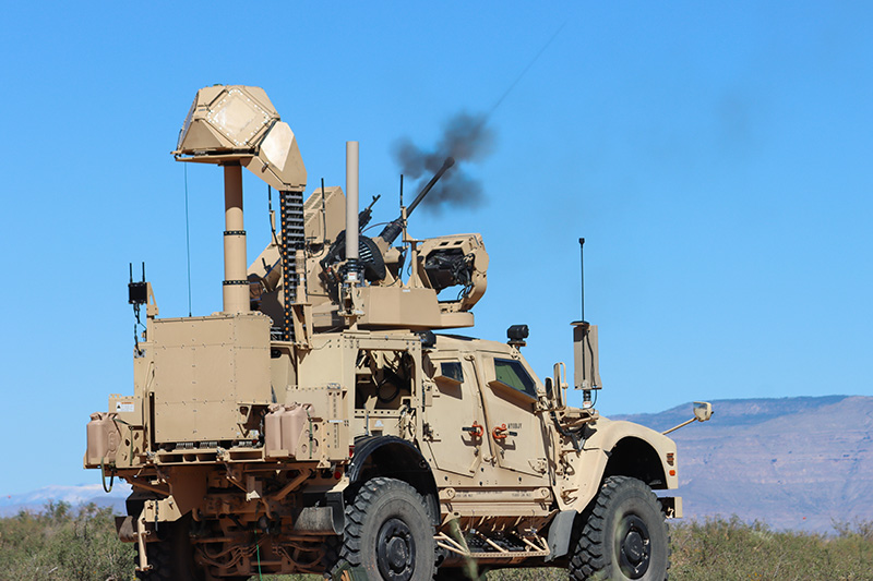
Small unmanned aerial systems (sUAS) have fundamentally changed the threat landscape across defense and critical infrastructure. Low-cost drones are now capable of surveillance, disruption, and coordinated attacks, often operating in environments where traditional defenses were never designed to respond.

Counter-UAS (C-UAS) systems are evolving quickly to address this challenge. Detection, tracking, and mitigation technologies continue to advance—but system performance ultimately depends on something less visible: the reliability of the interconnect systems that enable those technologies to function as a cohesive unit.

The core takeaway: counter-drone systems fail at the interfaces first. Interconnect design determines whether the system works when it matters.

The Shift in Drone Threat Complexity

Modern drone threats are not defined by a single platform, but by adaptability and scale.

Key characteristics

  • Low-cost, widely available platforms enabling rapid deployment
  • Swarm capability that stresses detection and response systems
  • Autonomous navigation reducing reliance on RF control links
  • Multi-mission payloads including ISR, electronic disruption, and kinetic impact

This has forced a transition from static perimeter defense to dynamic, layered countermeasures that operate continuously and in real time.

UAS Systems

What Counter-UAS Systems Must Deliver

C-UAS platforms integrate multiple subsystems, each dependent on uninterrupted electrical and signal performance.

Core system layers

  • Detection: radar, RF sensing, EO/IR systems
  • Identification: signal classification and threat validation
  • Tracking: continuous positional awareness and trajectory prediction
  • Mitigation: jamming, spoofing, or physical neutralization

These subsystems must operate simultaneously, exchanging high-speed data and maintaining stable RF performance under changing conditions.

Why Interconnect Systems Define Reliability

Most system failures in field-deployed C-UAS platforms do not originate in the sensors or processors—they occur at connection points.

Common failure modes

  • EMI leakage across connector interfaces
  • RF signal degradation due to impedance mismatch
  • Moisture ingress at cable transitions
  • Connector disengagement under vibration
  • Insulation breakdown in high-temperature zones

These issues are compounded in mobile deployments, outdoor environments, and electromagnetically dense operating conditions.

Counter-UAS Platforms

Core Interconnect Requirements for Counter-UAS Platforms

RF Signal Integrity

Detection and mitigation rely on consistent RF performance.

Design requirements include:

  • Controlled impedance throughout cable assemblies
  • Continuous shielding across connectors and enclosures
  • Low insertion loss and minimal signal distortion

High-performance connectors from manufacturers like Amphenol—including MIL-DTL-38999 Series III platforms, VITA connectors, and WaSP microminiature connectors—are commonly used in defense-grade systems. Performance, however, depends on how these components are integrated into the overall assembly.

Environmental Sealing and Protection

C-UAS systems are frequently deployed in harsh, exposed environments.

Required protections include:

  • IP/NEMA-rated sealing against moisture and contaminants
  • Resistance to dust, chemicals, and corrosion
  • Long-term durability under temperature extremes

Solutions such as overmolded cable assemblies eliminate ingress points by sealing critical transitions between cable and connector.

Power and Signal Integration

Modern systems require simultaneous transmission of multiple electrical functions:

  • High-current power for mitigation systems
  • High-speed data for sensing and analytics
  • RF signals for detection and countermeasures

This drives the need for hybrid cable assemblies, which consolidate multiple pathways into a single engineered solution, reducing size, weight, and failure points.

Mechanical Reliability Under Dynamic Conditions

Many C-UAS systems are mounted on vehicles or designed for rapid deployment, introducing continuous vibration and mechanical stress.

Failure risks include:

  • Conductor fatigue at termination points
  • Connector loosening over time
  • Abrasion and insulation wear

Integrated strain relief and routing strategies are essential. Solutions like molded breakout and strain relief systems help prevent localized stress failures.

EMI Shielding and Grounding Continuity

C-UAS systems operate in contested electromagnetic environments where both detection and mitigation generate interference.

Design priorities include:

  • Continuous shielding across all interconnect interfaces
  • Proper grounding across cables, connectors, and enclosures
  • Suppression of internal and external EMI sources

Technologies such as EMI shielding and metal braiding are critical—but only when implemented as part of a complete system design.

The Integration Gap

Many system-level failures can be traced back to fragmented design approaches:

  • Connectors selected independently of cable architecture
  • Materials added after initial design to solve sealing or EMI issues
  • Multiple vendors introducing tolerance mismatches
  • Lack of validation at the system level

This creates hidden vulnerabilities—particularly at transition points between components.

Proven Components

Integrating Proven Components into System-Level Solutions

High-performance components from suppliers such as Amphenol are widely used in defense systems. These components are engineered to meet demanding specifications such as MIL-DTL-38999 and MIL-PRF-2950.

XACT integrates these components into complete interconnect systems by combining:

  • Connector platforms from proven manufacturers
  • Application-specific cable design and routing
  • Environmental sealing and strain relief
  • System-level validation across electrical, mechanical, and environmental conditions

This includes:

FAQ: Testing and Reliability at XACT EMS

Defense-grade systems often use MIL-DTL-38999 Series III connectors, VITA connectors for modular architectures, and WaSP microminiature connectors for space-constrained designs. These connector platforms are selected for their durability, environmental sealing, and consistent electrical performance in harsh operating conditions.

Counter-UAS platforms operate in dense electromagnetic environments where detection and jamming occur simultaneously. Without proper shielding and grounding continuity, interference can degrade signal integrity, reduce detection accuracy, and limit mitigation effectiveness.

MIL-DTL-38999 is a military specification for circular connectors designed for harsh environments. Series III connectors are commonly used in defense systems due to their high vibration resistance, secure coupling mechanisms, and ability to maintain performance in extreme conditions.

Fiber optic connectors, often specified under MIL-PRF-2950, are used in systems requiring high-speed data transmission and immunity to electromagnetic interference. While XACT does not manufacture fiber optic cables, these connectors are often integrated into broader system architectures alongside copper-based cable assemblies.

Hybrid cable assemblies combine power, signal, and RF transmission into a single integrated solution. This reduces system complexity, simplifies routing, and minimizes potential failure points.

Overmolding encapsulates the transition between cable and connector, providing environmental sealing, strain relief, and mechanical protection. This is critical in applications exposed to moisture, vibration, and temperature extremes.

System Reliability Starts at the Interface

Counter-UAS systems are only as effective as their weakest connection point.

As drone threats continue to evolve, performance requirements will increase—not just in detection capability, but in reliability under real-world conditions. Systems must operate continuously without failure at critical moments.

That requires interconnect systems engineered from the start as part of the overall design—not added after the fact.

Engineering a Hermetic, Pressure-Rated Cable Assembly for Subsea Weld Inspection Probes

XACT engineered a fully hermetic, pressure-rated cable assembly for a subsea weld inspection probe used in harsh industrial and offshore environments. The redesigned interconnect system was developed to eliminate water ingress risk, withstand significant hydrostatic pressure, and preserve signal stability for a precision electromagnetic inspection platform.

The project required non-standard encapsulation methods and iterative engineering refinement before achieving a validated production-ready design.

Program Overview

A manufacturer of advanced non-destructive testing (NDT) instrumentation required a ruggedized cable assembly for a diver-operated weld inspection probe deployed underwater.

The probe is designed to inspect surface-breaking cracks within ground welds on submerged structures. Because inspection accuracy depends on stable electromagnetic measurements, the cable assembly must maintain consistent electrical performance while operating under pressure and exposure to moisture.

The engagement was executed through our Engineering Design Services team, combining interconnect design, encapsulation process development, and material optimization.

The assembly required:

  • Full hermetic sealing
  • Resistance to hydrostatic pressure equivalent to approximately 900 meters
  • Mechanical durability under handling and bending
  • Stable signal transmission for EMI-sensitive measurements

The Challenge

Traditional thermoplastic overmolded designs were evaluated but did not meet environmental performance targets for subsea deployment.

Primary risks included:

  • Hydrostatic compression creating micro-leak pathways
  • Voids within molded transitions
  • Adhesion failure between cable jacket and encapsulation material
  • Moisture ingress impacting signal amplitude and measurement accuracy
  • Mechanical stress concentration at the cable-to-probe interface

In this application, even minor moisture intrusion can cause signal drift or inconsistent readings. The interconnect needed to function as a structural and environmental barrier — not simply a termination.

The Engineering Solution

XACT developed a custom epoxy-potted cable assembly using a specialized potting and application process in place of conventional molded materials.

The redesigned termination incorporated:

  • Custom mold tooling for controlled encapsulation geometry
  • Full epoxy potting to eliminate void formation
  • Material selection optimized for compressive strength and adhesion
  • Controlled cure methodology to reduce internal stress
  • Iterative prototyping and refinement prior to final validation

This solution builds upon XACT’s expertise in Overmolded Cable Assemblies and advanced encapsulation strategies used in Rugged and Harsh Environment Assembly Solutions.

Where signal-sensitive systems require additional shielding reinforcement, integrated EMI and Metal Braiding Solutions can be incorporated to preserve electrical stability in high-interference environments.

The final design created a structurally reinforced, fully encapsulated termination capable of resisting hydrostatic compression while preventing moisture-driven degradation.

Validation

The completed cable assembly was pressure tested to simulate hydrostatic conditions equivalent to approximately 900 meters of depth.

The assembly successfully passed validation without leakage or structural compromise.

Following evaluation, the customer approved the initial production configuration and indicated that additional probe variants may be developed using the validated architecture.

System-Level Reliability Considerations

Subsea inspection systems require coordinated control of sealing, shielding, mechanical strain relief, and thermal stability.

Where enclosure-level environmental sealing is required, precision shielded gasket solutions or dispensed form-in-place gaskets can be integrated at housing interfaces to maintain environmental protection and EMI continuity.

If internal electronics generate heat within sealed housings, engineered thermal management solutions can be applied to stabilize operating temperatures and reduce long-term drift.

Where broader electromagnetic control is required, coordinated EMI shielding solutions may be incorporated at the system level.

Through an integrated materials and interconnect strategy, environmental protection, electrical performance, and mechanical durability are engineered together rather than addressed independently.

Results

  • Successful hydrostatic pressure validation
  • Hermetic sealing achieved
  • Improved mechanical reinforcement at termination
  • Reduced risk of moisture-driven signal instability
  • Platform architecture supporting future probe variants

Rail platforms are designed for 30–40 years of service life.

Your cable assemblies are expected to survive every one of them.

Between high-vibration undercarriage routing, washdown exposure, traction power EMI, thermal cycling, and repeated maintenance handling, rail interconnect systems operate in conditions far more severe than most industrial environments. Yet once qualified, they are often locked into a platform for decades.

When harness failures occur, they rarely fail in isolation. They trigger troubleshooting cycles, service disruptions, parts obsolescence challenges, and—in signaling applications—potential safety exposure. In rolling stock programs, redesigning or requalifying an interconnect after platform release can be significantly more disruptive and expensive than engineering it correctly upfront.

For rail OEMs, signaling integrators, and depot MRO teams, reliability is not about selecting a “tough cable.” It is about engineering a custom cable assembly system that accounts for vibration, ingress, EMI, routing constraints, serviceability, and long-term configuration control from day one.

The most common rail interconnect failures are predictable. And when addressed at the design stage, they can be engineered out before they ever reach the field.

The 6 Most Common Rail Cable Assembly Failure Modes — and How to Engineer Them Out

1. Vibration Fatigue at Connector Transitions

The Problem

Rail vehicles and wayside systems experience:

  • Continuous vibration
  • Shock loading
  • Micro-movement at clamp points
  • High-frequency harmonics from traction systems

Failure typically initiates at:

  • Connector backshell exits
  • Strain relief transitions
  • Harness branch points
  • Rigid-to-flex transitions

Intermittent faults are often the first symptom—making diagnosis costly and time-consuming.

Engineering Solutions

  • Purpose-built strain relief geometry
  • Targeted overmolding at high-stress transitions
  • Branch design optimized for real routing constraints
  • Controlled termination processes to ensure repeatability
  • Mechanical support strategy integrated into harness design

Overmolding is particularly effective when engineered for stress distribution rather than cosmetic sealing.

Learn more about engineered transition protection in our Overmolded Cable Assemblies solutions.

2. Moisture Ingress and Connector Corrosion

The Problem

Rail systems are exposed to:

  • Washdown procedures
  • Outdoor weather
  • Condensation cycles
  • Road debris and splash zones

Ingress failures often originate not at the connector face, but at:

  • Cable-to-connector interfaces
  • Inadequate backshell sealing
  • Improper grommet sizing
  • Inconsistent assembly torque or potting

Engineering Solutions

  • Sealing the entire interface system—not just the connector
  • Booted or overmolded transition zones
  • Environmental validation aligned with real deployment conditions
  • Defined assembly controls for repeatability

For harsh-environment rail builds, see: Rugged and Harsh Environment Assembly Solutions.

3. Abrasion in Undercarriage and Wayside Routing

The Problem

Abrasion damage rarely occurs randomly. It is usually traceable to:

  • Frame pass-through points
  • Clamp edges
  • Vibration-driven rubbing
  • Maintenance handling

Over time, jacket wear exposes shielding and conductors.

Engineering Solutions

  • Abrasion-resistant sleeving in known contact zones
  • Strain brackets and routing control strategies
  • Protective transitions at bulkheads
  • Serviceability-focused harness layout

Protective sleeving and tubing options can be integrated directly into build specifications.

4. EMI and Signal Integrity Failures in Train Control Systems

The Problem

PTC, CBTC, TCMS, and signaling systems operate in high-EMI environments due to:

  • Traction power systems
  • High-current switching
  • Nearby RF communication equipment

Improper shielding termination or inconsistent grounding strategies can result in:

  • Data corruption
  • False fault indications
  • Reduced system reliability

Engineering Solutions

  • Defined shield termination architecture
  • Controlled 360° shield bonding where required
  • Ground strategy aligned to system integrator specifications
  • Low-noise cable assemblies built for signal integrity

See our experience in signal-focused builds within the Communications & Telecom Sector

5. Thermal Degradation at High-Current Interfaces

The Problem

High-current traction and auxiliary power systems generate localized heat at:

  • Crimp interfaces
  • Terminal blocks
  • Connector contacts

Improper termination or underspecified conductors can accelerate insulation breakdown and reduce service life.

Engineering Solutions

  • Correct conductor sizing for duty cycle
  • Crimp validation and pull-test documentation
  • Thermal-aware routing inside enclosures
  • High-current rated connectors and assemblies

XACT supports high-current and mixed power/signal harness builds through our Custom Cable Assemblies program.

6. Documentation and Configuration Drift Over Long Service Life

The Problem

Rail platforms evolve over decades. Without disciplined configuration control:

  • Harness revisions drift
  • Replacement builds mismatch
  • Labeling inconsistencies create service errors
  • Obsolescence introduces undocumented substitutions

This is one of the most common causes of depot frustration.

Engineering Solutions

  • Controlled drawings and revision management
  • Traceable build documentation
  • Test records retained for lifecycle support
  • Kitting strategies for MRO programs

For lifecycle extension and rebuild programs, explore: Cable Repair & Recertification

Rail-Specific Compliance Considerations

Depending on application lane, rail interconnect programs may require:

  • EN 45545 fire/smoke compliance (rolling stock)
  • AAR standards (freight)
  • Documented EMI/EMC awareness
  • Ingress protection validation
  • Long-term traceability and configuration discipline

Engineering for compliance must begin at the design stage—not after platform qualification.

Designing for the Rail Lifecycle

Rail interconnect reliability is not about preventing “cable damage.”

It is about designing:

  • For 30–40 year service life
  • For depot-level serviceability
  • For configuration control across program revisions
  • For environmental realities—not lab assumptions

The difference between commodity cable supply and engineered rail harness systems is lifecycle thinking.

When vibration, EMI, moisture, and thermal loads are accounted for at the architecture stage, failure rates drop, troubleshooting cycles shorten, and MRO operations stabilize.

Rail platforms reward disciplined engineering.

They punish shortcuts.

Ready to engineer failure-resistant cable assemblies for your rail platform?

Talk to XACT’s engineering team about custom harness design, rugged overmolding, high-current builds, and long-term MRO support.

Surface and underground mining operations may extract similar materials, but the electrical environments they create are fundamentally different. From regulatory requirements to mechanical stress profiles, interconnect systems must be engineered differently depending on where they operate.

Designing cable assemblies, harnesses, and terminations without accounting for these differences increases the risk of premature failure, MSHA citations, and avoidable downtime. The most reliable mining programs treat surface and underground interconnect systems as distinct engineering challenges—each with its own compliance framework, environmental exposures, and dominant failure modes.

Regulatory Differences: Coal vs Metal/Nonmetal, Surface vs Underground

Electrical compliance in mining is governed primarily by the Mine Safety and Health Administration (MSHA). Requirements differ based on mine type and location.

Underground Coal Mines (30 CFR Part 75)

Underground coal operations face:

  • Strict flame-resistance requirements
  • Emphasis on trailing cable protection
  • Increased scrutiny on permissibility and ignition risk
  • Higher inspection sensitivity to damaged insulation or splices

Fire propagation risk in confined environments drives many of these requirements. Cable systems must limit flame spread and maintain grounding integrity under wet, abrasive conditions.

Surface Coal Mines (30 CFR Part 77)

Surface coal operations focus on:

  • Protection against physical damage
  • Grounding and bonding integrity
  • Guarding of energized conductors
  • Safe temporary power installations

Flame spread remains important, but open-air conditions reduce confinement risk.

Metal and Nonmetal Mines (30 CFR Parts 56 and 57)

Metal and nonmetal operations emphasize:

  • Protection from mechanical damage
  • Proper insulation and guarding
  • Ground-fault protection
  • Maintenance of wiring in crushers, conveyors, and process plants

The regulatory framework alone justifies differentiated interconnect strategies between underground and surface environments.

Mechanical Stress Profiles: Confined Flex vs Open-Site Impact

Underground Mining: High Flex + High Moisture

Underground interconnect systems are exposed to:

  • Continuous flexing in trailing cables
  • Sharp bend radii in confined routing paths
  • Constant moisture and water ingress risk
  • Rock abrasion and falling debris
  • Frequent machine movement and cable dragging

Common underground equipment includes:

  • Continuous miners
  • Shuttle cars
  • Load-haul-dump (LHD) vehicles
  • Bolters and drills

Trailing cables and high-flex harnessing are dominant architectures. Mechanical fatigue at termination points is one of the most frequent failure sources.

Engineering controls typically include:

  • High-strand-count conductors for flex endurance
  • Molded strain relief to prevent conductor breakage
  • Abrasion-resistant jacketing
  • Sealed or overmolded transitions at connectors

For assemblies designed specifically for these environments, see:

Rugged and Harsh Environment Assembly Solutions

Surface Mining: Impact, UV, and Vehicle Interaction

Surface mining introduces different mechanical risks:

  • UV degradation
  • Freeze-thaw cycling
  • Long cable runs exposed to vehicle traffic
  • Crushing risk from haul trucks and loaders
  • Steel structure abrasion
  • Dust contamination

Cable runs are often longer and more semi-permanent. While flex demands may be lower than underground trailing cables, exposure to environmental degradation is significantly higher.

Surface design priorities often include:

  • UV-resistant jacket materials
  • Crush protection or armored routing
  • Controlled strain relief at panel and junction transitions
  • Protective tubing and sleeving

Protective options include:

Tubing & Sleeving Solutions

Electrical Risk Differences

Underground Electrical Risk Profile

  • High humidity increases leakage current risk
  • Ground-fault sensitivity is critical
  • Flame propagation risk in confined airspace
  • Greater inspection scrutiny on damaged insulation

Failure of grounding continuity is especially serious underground. Proper termination practices and robust connector systems are essential.

Where high-current power interfaces are involved, properly engineered terminations and sealed strain relief are critical.

See: Overmolded Cable Assemblies

Surface Electrical Risk Profile

  • Voltage drop concerns over long distribution runs
  • Environmental degradation of insulation
  • Contamination of connectors from dust and mud
  • Intermittent grounding failures due to corrosion

Surface systems often incorporate larger distribution assemblies, portable substations, and panelized power systems.Termination integrity and environmental sealing remain critical but are stressed differently than underground.

Dominant Failure Modes by Environment

Environment Most Common Failure Drivers Typical Root Cause
Underground Conductor fatigue Repeated flex at machine interface
Underground Jacket breach Dragging on rock or steel edges
Underground Moisture ingress Inadequate sealing at terminations
Surface UV cracking Prolonged sunlight exposure
Surface Crushing damage Vehicle traffic over cable runs
Surface Connector contamination Dust and mud ingress

Recognizing these patterns allows interconnect systems to be engineered proactively rather than reactively.

Architecture Differences: Trailing Cable vs Distributed Assemblies

Underground Architecture

  • High-flex trailing cable systems
  • Frequent disconnect/reconnect cycles
  • Compact routing through confined machine frames
  • Greater reliance on molded breakouts and sealed interfaces

Hybrid power + control harnessing is common in mobile underground equipment.

See: Hybrid Cable Solutions

Surface Architecture

  • Longer, semi-permanent runs
  • Panel-to-equipment distribution
  • Greater emphasis on modular skids and junction boxes
  • Lower flex frequency but higher exposure risk

Surface processing plants introduce additional fixed harness and panel wiring assemblies.

Compliance Is a Lifecycle Issue, Not an Installation Event

Both surface and underground environments share one reality:

Electrical systems that are compliant on day one can become non-compliant through wear, damage, or field modification.

Effective compliance strategy includes:

  • Inspection intervals matched to environment severity
  • Controlled repair procedures
  • Documented rebuild and recertification programs
  • Traceable harness assemblies built to defined workmanship standards

For lifecycle support:

Cable Repair & Recertification

Engineering Implications for Mining Interconnect Design

Designing the same cable assembly for both surface and underground use without modification introduces unnecessary risk.

Instead, specification should consider:

  • Flex cycle requirements
  • Flame-resistance expectations
  • Environmental exposure (UV vs moisture dominance)
  • Routing method (dragging vs fixed support)
  • Inspection cadence
  • Termination access and strain relief design

When these variables are defined early, interconnect systems become predictable and durable rather than reactive maintenance items.

For full custom interconnect development:

Custom Cable Assemblies

Engineering the Right Interconnect for the Right Mine

Surface and underground mining may operate under the same regulatory umbrella, but they impose fundamentally different electrical and mechanical demands. The most reliable programs treat these environments separately during specification, validation, and maintenance planning.

Engineering cable assemblies to match real environmental stress—rather than defaulting to generic “mining-rated” solutions—reduces citation risk, improves uptime, and extends service life across the fleet.