If you’re comparing overmolding, potting, and heat shrink, you’re not just choosing a process—you’re deciding how your cable assembly will hold up under real conditions.

Each method solves a different problem. The mistake is assuming they’re interchangeable.

Overmolding: When You Need Strength + Sealing

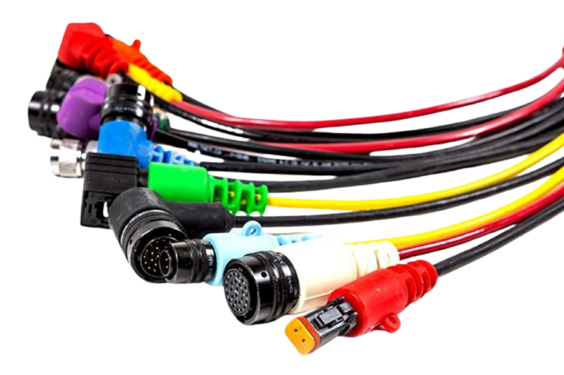
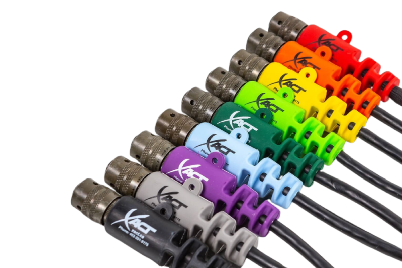
Overmolding creates a sealed, bonded transition between cable and connector. It’s the go-to for assemblies that can’t fail in the field.

Best fit:

  • Outdoor or harsh environments
  • High vibration or repeated movement
  • Applications requiring sealing (IP-rated)

What you get:

  • Built-in strain relief
  • Strong environmental sealing
  • Long-term durability

Tradeoff:

  • Higher upfront tooling cost
  • Not reworkable
Overmolding vs Potting

Potting: When Internal Protection Matters

Potting fills internal cavities with resin to protect terminations, electronics, or sensitive components.

Best fit:

  • Internal component protection
  • Vibration or shock exposure
  • High-voltage insulation support

What you get:

  • Encapsulation of internal components
  • Moisture and chemical resistance
  • Added electrical insulation

Tradeoff:

  • Doesn’t provide strong external strain relief
  • Adds weight
  • Hard to inspect or rework

Heat Shrink: When You Need a Simple, Flexible Option

Heat shrink is widely used because it’s fast and cost-effective—but it’s not designed for demanding environments.

Best fit:

  • Basic insulation or bundling
  • Controlled environments
  • Prototyping or low-cost builds

What you get:

  • Quick installation
  • Low cost
  • Flexible application

Tradeoff:

  • Minimal strain relief
  • Limited environmental sealing
  • Shorter lifespan under stress
Overmolding vs Potting

What Actually Drives the Decision

Forget the terminology—focus on what matters in your application:

  • Strain relief needed? → Overmolding
  • Internal protection needed? → Potting
  • Cost-sensitive and low stress? → Heat shrink

Why These Methods Get Misapplied

Most failures come from one issue:

Choosing based on cost instead of risk.

  • Heat shrink used where mechanical stress exists
  • Potting expected to handle external strain
  • Overmolding skipped to reduce upfront cost

That decision usually shows up later as:

  • Field failures
  • Maintenance costs
  • Downtime

When One Method Isn’t Enough

In demanding applications, combining methods is common:

  • Overmolding + potting → full protection (external + internal)
  • Heat shrink + overmolding → added insulation + strain relief

Quick Decision Guide

  • Movement + environment → Overmolding
  • Internal electronics → Potting
  • Light-duty / cost-driven → Heat shrink
  • Critical system → Combine methods

Need Help Choosing?

If you’re evaluating these options, you’re already past generic solutions.

FAQ

Overmolding protects the external cable-to-connector transition, providing strain relief and sealing. Potting protects internal components, such as terminations or electronics, by encapsulating them in resin.

Heat shrink is suitable for basic insulation and bundling, but it does not provide strong strain relief or long-term protection in harsh environments.

Use overmolded assemblies when you need:

  • Environmental sealing
  • Mechanical strength
  • Long-term durability in harsh conditions

Yes. Many high-reliability assemblies use both:

  • Potting for internal protection
  • Overmolding for external durability and strain relief

Overmolding is typically the most durable option for external protection, especially in environments with vibration, moisture, or mechanical stress.
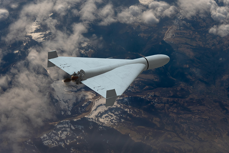
Small unmanned aerial systems (sUAS) have fundamentally changed the threat landscape across defense and critical infrastructure. Low-cost drones are now capable of surveillance, disruption, and coordinated attacks, often operating in environments where traditional defenses were never designed to respond.

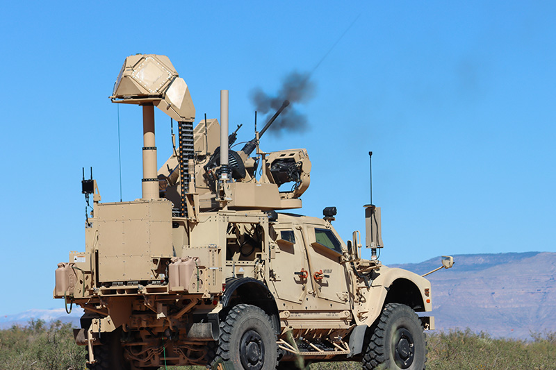
Counter-UAS (C-UAS) systems are evolving quickly to address this challenge. Detection, tracking, and mitigation technologies continue to advance—but system performance ultimately depends on something less visible: the reliability of the interconnect systems that enable those technologies to function as a cohesive unit.

The core takeaway: counter-drone systems fail at the interfaces first. Interconnect design determines whether the system works when it matters.

The Shift in Drone Threat Complexity

Modern drone threats are not defined by a single platform, but by adaptability and scale.

Key characteristics

  • Low-cost, widely available platforms enabling rapid deployment
  • Swarm capability that stresses detection and response systems
  • Autonomous navigation reducing reliance on RF control links
  • Multi-mission payloads including ISR, electronic disruption, and kinetic impact

This has forced a transition from static perimeter defense to dynamic, layered countermeasures that operate continuously and in real time.

UAS Systems

What Counter-UAS Systems Must Deliver

C-UAS platforms integrate multiple subsystems, each dependent on uninterrupted electrical and signal performance.

Core system layers

  • Detection: radar, RF sensing, EO/IR systems
  • Identification: signal classification and threat validation
  • Tracking: continuous positional awareness and trajectory prediction
  • Mitigation: jamming, spoofing, or physical neutralization

These subsystems must operate simultaneously, exchanging high-speed data and maintaining stable RF performance under changing conditions.

Why Interconnect Systems Define Reliability

Most system failures in field-deployed C-UAS platforms do not originate in the sensors or processors—they occur at connection points.

Common failure modes

  • EMI leakage across connector interfaces
  • RF signal degradation due to impedance mismatch
  • Moisture ingress at cable transitions
  • Connector disengagement under vibration
  • Insulation breakdown in high-temperature zones

These issues are compounded in mobile deployments, outdoor environments, and electromagnetically dense operating conditions.

Counter-UAS Platforms

Core Interconnect Requirements for Counter-UAS Platforms

RF Signal Integrity

Detection and mitigation rely on consistent RF performance.

Design requirements include:

  • Controlled impedance throughout cable assemblies
  • Continuous shielding across connectors and enclosures
  • Low insertion loss and minimal signal distortion

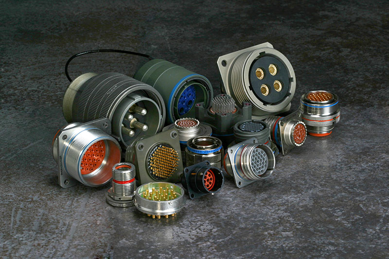
High-performance connectors from manufacturers like Amphenol—including MIL-DTL-38999 Series III platforms, VITA connectors, and WaSP microminiature connectors—are commonly used in defense-grade systems. Performance, however, depends on how these components are integrated into the overall assembly.

Environmental Sealing and Protection

C-UAS systems are frequently deployed in harsh, exposed environments.

Required protections include:

  • IP/NEMA-rated sealing against moisture and contaminants
  • Resistance to dust, chemicals, and corrosion
  • Long-term durability under temperature extremes

Solutions such as overmolded cable assemblies eliminate ingress points by sealing critical transitions between cable and connector.

Power and Signal Integration

Modern systems require simultaneous transmission of multiple electrical functions:

  • High-current power for mitigation systems
  • High-speed data for sensing and analytics
  • RF signals for detection and countermeasures

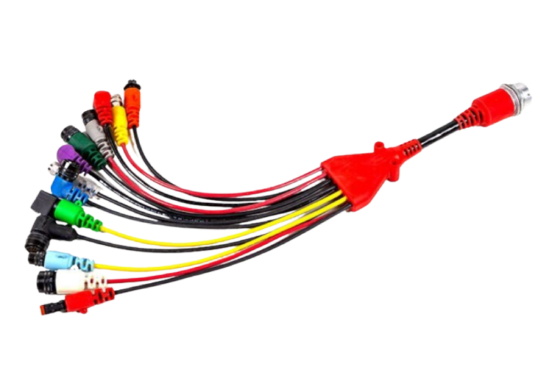
This drives the need for hybrid cable assemblies, which consolidate multiple pathways into a single engineered solution, reducing size, weight, and failure points.

Mechanical Reliability Under Dynamic Conditions

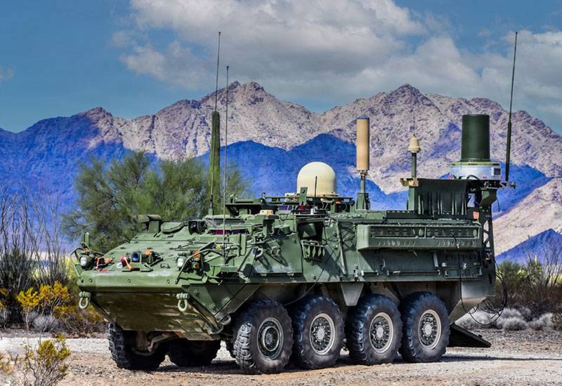
Many C-UAS systems are mounted on vehicles or designed for rapid deployment, introducing continuous vibration and mechanical stress.

Failure risks include:

  • Conductor fatigue at termination points
  • Connector loosening over time
  • Abrasion and insulation wear

Integrated strain relief and routing strategies are essential. Solutions like molded breakout and strain relief systems help prevent localized stress failures.

EMI Shielding and Grounding Continuity

C-UAS systems operate in contested electromagnetic environments where both detection and mitigation generate interference.

Design priorities include:

  • Continuous shielding across all interconnect interfaces
  • Proper grounding across cables, connectors, and enclosures
  • Suppression of internal and external EMI sources

Technologies such as EMI shielding and metal braiding are critical—but only when implemented as part of a complete system design.

The Integration Gap

Many system-level failures can be traced back to fragmented design approaches:

  • Connectors selected independently of cable architecture
  • Materials added after initial design to solve sealing or EMI issues
  • Multiple vendors introducing tolerance mismatches
  • Lack of validation at the system level

This creates hidden vulnerabilities—particularly at transition points between components.

Proven Components

Integrating Proven Components into System-Level Solutions

High-performance components from suppliers such as Amphenol are widely used in defense systems. These components are engineered to meet demanding specifications such as MIL-DTL-38999 and MIL-PRF-2950.

XACT integrates these components into complete interconnect systems by combining:

  • Connector platforms from proven manufacturers
  • Application-specific cable design and routing
  • Environmental sealing and strain relief
  • System-level validation across electrical, mechanical, and environmental conditions

This includes:

FAQ: Testing and Reliability at XACT EMS

Defense-grade systems often use MIL-DTL-38999 Series III connectors, VITA connectors for modular architectures, and WaSP microminiature connectors for space-constrained designs. These connector platforms are selected for their durability, environmental sealing, and consistent electrical performance in harsh operating conditions.

Counter-UAS platforms operate in dense electromagnetic environments where detection and jamming occur simultaneously. Without proper shielding and grounding continuity, interference can degrade signal integrity, reduce detection accuracy, and limit mitigation effectiveness.

MIL-DTL-38999 is a military specification for circular connectors designed for harsh environments. Series III connectors are commonly used in defense systems due to their high vibration resistance, secure coupling mechanisms, and ability to maintain performance in extreme conditions.

Fiber optic connectors, often specified under MIL-PRF-2950, are used in systems requiring high-speed data transmission and immunity to electromagnetic interference. While XACT does not manufacture fiber optic cables, these connectors are often integrated into broader system architectures alongside copper-based cable assemblies.

Hybrid cable assemblies combine power, signal, and RF transmission into a single integrated solution. This reduces system complexity, simplifies routing, and minimizes potential failure points.

Overmolding encapsulates the transition between cable and connector, providing environmental sealing, strain relief, and mechanical protection. This is critical in applications exposed to moisture, vibration, and temperature extremes.

System Reliability Starts at the Interface

Counter-UAS systems are only as effective as their weakest connection point.

As drone threats continue to evolve, performance requirements will increase—not just in detection capability, but in reliability under real-world conditions. Systems must operate continuously without failure at critical moments.

That requires interconnect systems engineered from the start as part of the overall design—not added after the fact.

Engineered for Harsh Environment Connectivity Without Compromise

The Xtreme M12 by Xact is not a generic M12 derivative—it’s an industrial-grade, field-hardened interconnect system engineered specifically for mission-critical reliability in the most punishing environments. Designed with engineers in mind, this overmolded M12 solution delivers mechanical resilience, electrical integrity, and form factor versatility beyond what commercial off-the-shelf connectors can provide.

🔍 Mechanical & Environmental Integrity

  • Overmolded Body with Integrated Strain Relief:
    Each Xtreme M12 features a robust overmolded thermoplastic body designed to protect internal contact systems against flex fatigue, mechanical stress, and ingress. The integrated strain relief prevents conductor fatigue at the cable entry point—ideal for dynamic applications in rail and heavy automation.
  • Sealing & Ingress Protection:
    Certified to IP67/IP68/IP69K, the Xtreme M12 resists high-pressure washdowns, oil, dust, mud, and chemical exposure—suitable for Class I Division 2 (CID2) and other hazardous locations.
  • Vibration & Shock Tolerance:
    Validated to exceed IEC 60068-2-6 and 2-27 standards, ensuring stable signal transmission under persistent vibration (e.g., rail trucks, tracked vehicles, rotary drilling).
  • Crush-Resistant Architecture:
    Shell and overmold withstand impact and compressive loads—surviving drops, crushing forces, and real-world mishandling common in field deployment.

🌐 Proven Across Operational Theaters

The Xtreme M12 has been field-deployed in:

  • Oil & Gas surface operations (frac spreads, control cabins, SCADA I/O)
  • Defense platforms, including mobile ground systems and targeting subsystems
  • Mining environments with corrosive dust and mechanical shock
  • Rail and transportation, exposed to vibration, freeze-thaw, and EMI
  • Industrial automation, robotics, and high-cycle motion loops

This is not speculative performance. These connectors have already survived where standard components routinely fail.

🔧 Configurable Variants Available

  • Connector Types: A-, B-, D-, X-, and custom keying options
  • Pin Counts: 3 to 12 contacts (shielded and unshielded)
  • Cable Assemblies: Available in PUR/PVC jacketed cable, TPE options, or custom overbraid for EMC-critical applications
  • Termination Styles: Straight, right-angle, panel-mount receptacles, and field-wireable options
  • Mating Interfaces: Brass-nickel-plated threaded coupling, coded for environmental sealing and reliable mating cycles

⚠️ Stop Relying on Commodity Connectors

If you’re specifying off-the-shelf or overseas-sourced M12s in a high-reliability system, you’re designing in a failure point. Xact’s Xtreme M12 is engineered for when standard M12s become the weakest link.

🧪 Engineered. Validated. Proven.

Built and tested under real-world load conditions—not just lab specs—the Xtreme M12 offers engineers confidence in long-term deployment without rework or failure-related downtime.

🔗 Contact Xact today for engineering samples, data sheets, or mechanical CAD files.


Optimize for reliability. Specify Xtreme.