


The Shift in Drone Threat Complexity
Modern drone threats are not defined by a single platform, but by adaptability and scale.
Key characteristics
- Low-cost, widely available platforms enabling rapid deployment
- Swarm capability that stresses detection and response systems
- Autonomous navigation reducing reliance on RF control links
- Multi-mission payloads including ISR, electronic disruption, and kinetic impact
This has forced a transition from static perimeter defense to dynamic, layered countermeasures that operate continuously and in real time.
What Counter-UAS Systems Must Deliver
C-UAS platforms integrate multiple subsystems, each dependent on uninterrupted electrical and signal performance.
Core system layers
- Detection: radar, RF sensing, EO/IR systems
- Identification: signal classification and threat validation
- Tracking: continuous positional awareness and trajectory prediction
- Mitigation: jamming, spoofing, or physical neutralization
These subsystems must operate simultaneously, exchanging high-speed data and maintaining stable RF performance under changing conditions.
Why Interconnect Systems Define Reliability
Most system failures in field-deployed C-UAS platforms do not originate in the sensors or processors—they occur at connection points.
Common failure modes
- EMI leakage across connector interfaces
- RF signal degradation due to impedance mismatch
- Moisture ingress at cable transitions
- Connector disengagement under vibration
- Insulation breakdown in high-temperature zones
These issues are compounded in mobile deployments, outdoor environments, and electromagnetically dense operating conditions.
Core Interconnect Requirements for Counter-UAS Platforms
RF Signal Integrity
Detection and mitigation rely on consistent RF performance.
Design requirements include:
- Controlled impedance throughout cable assemblies
- Continuous shielding across connectors and enclosures
- Low insertion loss and minimal signal distortion
High-performance connectors from manufacturers like Amphenol—including MIL-DTL-38999 Series III platforms, VITA connectors, and WaSP microminiature connectors—are commonly used in defense-grade systems. Performance, however, depends on how these components are integrated into the overall assembly.
Environmental Sealing and Protection
C-UAS systems are frequently deployed in harsh, exposed environments.
Required protections include:
- IP/NEMA-rated sealing against moisture and contaminants
- Resistance to dust, chemicals, and corrosion
- Long-term durability under temperature extremes
Solutions such as overmolded cable assemblies eliminate ingress points by sealing critical transitions between cable and connector.
Power and Signal Integration
Modern systems require simultaneous transmission of multiple electrical functions:
- High-current power for mitigation systems
- High-speed data for sensing and analytics
- RF signals for detection and countermeasures
This drives the need for hybrid cable assemblies, which consolidate multiple pathways into a single engineered solution, reducing size, weight, and failure points.
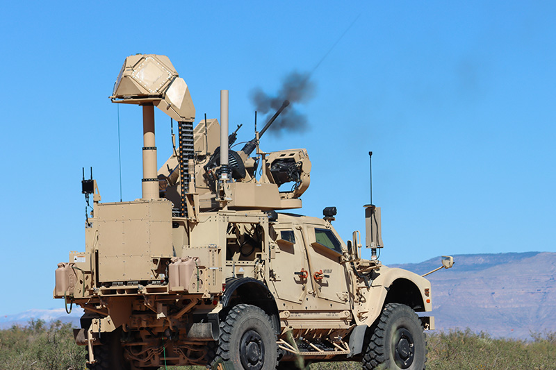
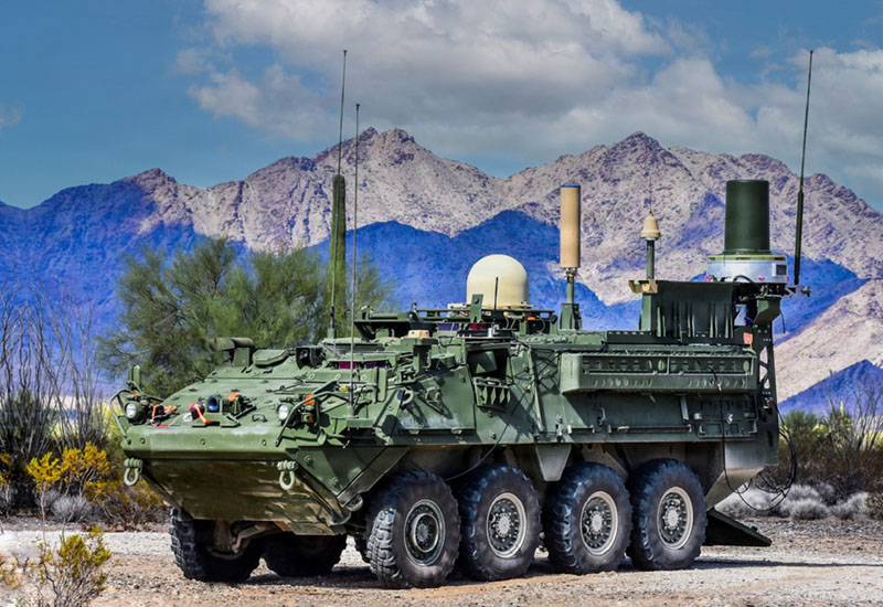
Mechanical Reliability Under Dynamic Conditions
Many C-UAS systems are mounted on vehicles or designed for rapid deployment, introducing continuous vibration and mechanical stress.
Failure risks include:
- Conductor fatigue at termination points
- Connector loosening over time
- Abrasion and insulation wear
Integrated strain relief and routing strategies are essential. Solutions like molded breakout and strain relief systems help prevent localized stress failures.
EMI Shielding and Grounding Continuity
C-UAS systems operate in contested electromagnetic environments where both detection and mitigation generate interference.
Design priorities include:
- Continuous shielding across all interconnect interfaces
- Proper grounding across cables, connectors, and enclosures
- Suppression of internal and external EMI sources
Technologies such as EMI shielding and metal braiding are critical—but only when implemented as part of a complete system design.
The Integration Gap
Many system-level failures can be traced back to fragmented design approaches:
- Connectors selected independently of cable architecture
- Materials added after initial design to solve sealing or EMI issues
- Multiple vendors introducing tolerance mismatches
- Lack of validation at the system level
This creates hidden vulnerabilities—particularly at transition points between components.
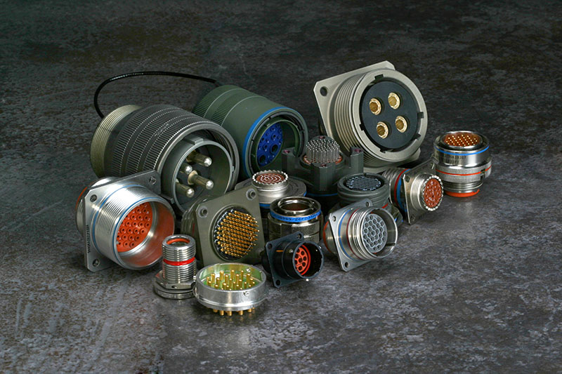
Integrating Proven Components into System-Level Solutions
High-performance components from suppliers such as Amphenol are widely used in defense systems. These components are engineered to meet demanding specifications such as MIL-DTL-38999 and MIL-PRF-2950.
XACT integrates these components into complete interconnect systems by combining:
- Connector platforms from proven manufacturers
- Application-specific cable design and routing
- Environmental sealing and strain relief
- System-level validation across electrical, mechanical, and environmental conditions
This includes:
- custom cable assemblies for application-specific builds
- military-grade cable assemblies for regulated programs
- rugged and harsh environment cable assemblies for extreme deployments
