Rail modernization projects rarely start from a clean slate.
Most fleets are decades old, built on legacy systems that weren’t designed for today’s technology. But replacing entire electrical systems isn’t practical—it’s expensive, slow, and disruptive to operations.
That’s why rail retrofit wiring comes down to one objective:
Replace what’s failing—without breaking everything else.
Why Legacy Harness Replacement Becomes a Bottleneck
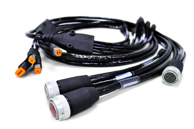
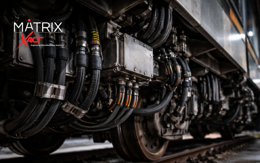
Rail systems rely on complex wiring harnesses that connect:
- Door control systems
- Lighting systems
- Control panels and modules
- Communication and signaling systems
Over time, these harnesses degrade due to:
- Vibration and mechanical stress
- Moisture and environmental exposure
- Material aging
- Obsolete connectors and components
When they fail, the issue isn’t just replacement—it’s compatibility.
The Real Risk: Turning a Retrofit Into a Redesign
Most retrofit programs don’t fail at the system level—they fail at the interconnect level.
If a replacement harness doesn’t match the original system, it creates:
- Connector mismatches
- Routing and fitment issues
- Electrical inconsistencies
- Installation delays
What should be a straightforward swap turns into engineering rework, redesign, and extended downtime.
The Right Approach: Form-Fit-Function Replacement
The most effective way to handle rail retrofit wiring is:
Match the original harness exactly—then improve performance where it matters.
Form-fit-function replacement ensures:
- Same geometry and physical layout (form)
- Same mounting and routing compatibility (fit)
- Same electrical behavior (function)
With upgrades in:
- Materials
- Sealing
- Durability
- Labeling and install clarity
This keeps the system stable while improving reliability.
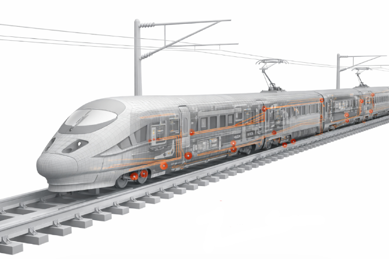
Where Retrofit Harnesses Are Used Most
Rail MRO and modernization programs consistently target the same systems:
Door Control Systems
- High cycle wear components
- Frequent failure points
- Retrofit kits reduce install time
Lighting and Interior Systems
- Transition to newer technologies
- Requires compatibility with legacy wiring
Control Panels and Modules
- Integration of updated electronics
- Requires stable interconnects
Legacy Panel Rewiring
- Replacement of obsolete components
- Requires exact interface matching
These are repeatable applications across entire fleets.
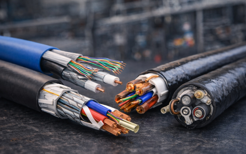
What Makes a Retrofit Cable Assembly Work
Successful retrofit assemblies are built for installation—not just function.
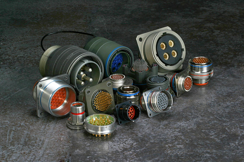
Exact Interface Matching
- Connector compatibility
- Pinout accuracy
- Mechanical fit
Pre-Labeled and Kitted Designs
- Faster installs
- Reduced technician error
- Consistent deployment across assets
Environmental Protection
- Sealed connections
- Vibration resistance
- Durable jacketing
Rapid Turnaround
- Aligns with maintenance schedules
- Reduces downtime
The Business Case: When Retrofit Makes Sense vs When Redesign Is the Better Move
Not every rail upgrade should follow the same path.
Retrofit (Form-Fit-Function Replacement)
Best when:
- The system architecture still works
- Specific components are failing or obsolete
- Downtime must be minimized
- Fleet-wide repeatability is required
Advantages:
- Lower engineering cost
- Faster deployment
- Minimal disruption
Redesign (System-Level Upgrade)
Best when:
- The system can’t support new technology
- Performance requirements have changed significantly
- Safety or compliance standards have evolved
- Multiple subsystems need to be upgraded together
Advantages:
- Enables full system optimization
- Supports new functionality
- Removes legacy limitations
The Practical Reality
Most rail programs combine both:
- Retrofit harness replacements to maintain compatibility
- Targeted redesigns where systems need to evolve
The goal isn’t to avoid redesign—it’s to avoid unnecessary redesign.
Why Rail MRO Demands Speed and Repeatability
Maintenance environments don’t allow for trial and error.
They require:
- Fast installation
- Clear documentation
- Minimal on-site engineering
That’s why depot-installable cable assemblies and pre-labeled retrofit kits are critical.
When done right, they:
- Reduce install time
- Eliminate guesswork
- Enable consistent upgrades across fleets
Where Retrofit Programs Break Down
Common failure points include:
- Incomplete legacy documentation
- Poor replication of original harness geometry
- Lack of labeling or install guidance
- Long lead times
- Underestimating environmental conditions
These problems show up during installation—not during planning.
What This Means for Rail Operators and MRO Providers
If you’re managing:
- Fleet modernization programs
- Maintenance operations
- System upgrades
Then interconnect strategy directly impacts:
- Downtime
- Labor efficiency
- Total program cost
Getting the harness right simplifies everything else.
Quick Retrofit Checklist
- Match legacy form-fit-function exactly
- Validate connector and pinout compatibility
- Use ruggedized materials
- Pre-label and kit assemblies
- Plan for repeatability across fleet upgrades
Need Help With a Retrofit Program?
Rail retrofit wiring projects don’t fail because of major systems—they fail at the interconnect level.
FAQ
What is rail retrofit wiring?
Rail retrofit wiring involves replacing or upgrading cable assemblies and wiring harnesses in existing rail systems without redesigning the entire electrical architecture.
What is a form-fit-function cable replacement?
It is a replacement that matches the original component’s physical design, mounting, and electrical performance so it can be installed without modifying surrounding systems.
Why are wire harnesses replaced in rail systems?
They are replaced due to wear, environmental exposure, obsolescence, or system upgrades that require improved reliability or compatibility.
What are retrofit cable kits?
Retrofit cable kits are pre-labeled, pre-configured cable assemblies designed for fast installation during maintenance or modernization work.
How do you avoid redesign during rail upgrades?
By using replacement harnesses that match the original system’s form, fit, and function, allowing upgrades without impacting surrounding components.
Why is labeling important in retrofit harnesses?
Labeling reduces installation errors, speeds up maintenance, and ensures consistent implementation across multiple assets or fleet upgrades.